


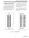
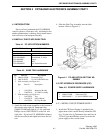
CABINETRY ASSEMBLY FOR CRT CONSOLE SYSTEMS
3-7
February 1996
Part No. 004-3039-274
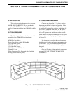
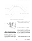
cabinetry consisting of a pie-shape sections along with
2 or more cabinet bays in-line before the turn, one (1)
stabilizer kit only is required at the end opposite the
pie-shaped section. For assembly purposes, each con-
sole that is required to have a stabilizer installed, is
identified with a label: Mount Stabilizer Leg Here
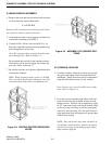
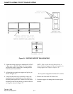
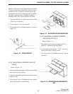
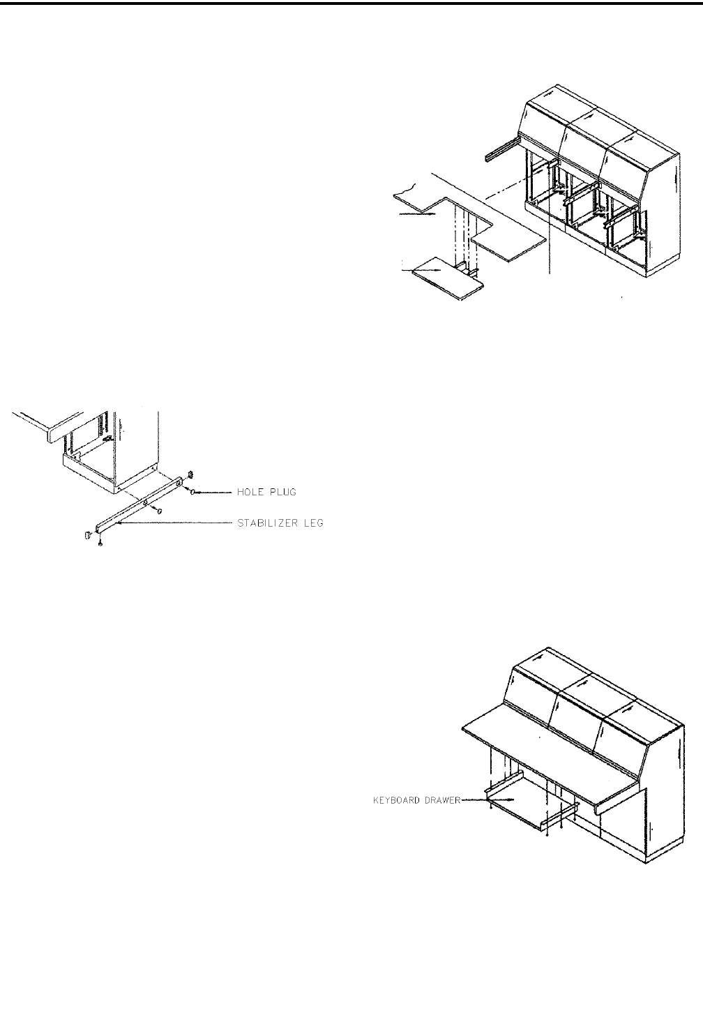
1. Align the stabilizer leg with the bottom holes of the
console bay as indicated.
2. Fasten with two (2) # -20x hex bolts.
3. Conceal the bolts by placing hole plugs as shown in
Figure 3-11.
Figure 3-11 STABILIZER KIT
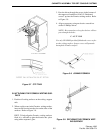
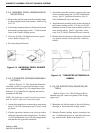
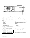
3.10.2 ADJUSTABLE KEYBOARD SEAT (OP-
TION 2)
Refer to Figure 3-12.
1. Mount the keyboard support rail (#2 short rail) in the
rear of the keyboard opening.
2. Align the adjustable keyboard seat with the writing
surface cutout.
3. Drive seven (7) #10 x 3/4 flakeboard screws up into
the wood using the pre-drilled holes.
Figure 3-12 ADJUSTABLE KEYBOARD SEAT
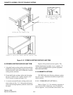
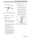
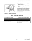
3.10.3 UNIVERSAL KEYBOARD DRAWER
MOUNTING (OPTION 3)
Refer to Figure 3-13.
1. Mount the #2 short keyboard support rails as in
Option 2, behind the keyboard drawer.
2. Position the keyboard drawer 1" back from the
front of the Formica writing surface.
3. Drive six (6) #10 x 3/4 flakeboard screws up into
the wood.
Figure 3-13 KEYBOARD DRAWER MOUNT-
ING