


CABINETRY ASSEMBLY FOR CRT CONSOLE SYSTEMS
3-2
February 1996
Part No. 004-3039-274
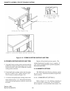
3.4 MAIN CONSOLE ASSEMBLY
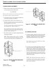
4. Remove the front and rear keylocked enclosure pan-
els from each bay and set them aside.
C A U T I O N
Keylocks will scratch keylock enclosure panels if they
are stacked or leaned against each other.
5. Accurately place the console section at its final loca-
tion before continuing with STEP 3.
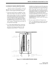
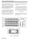
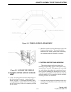
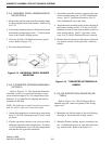
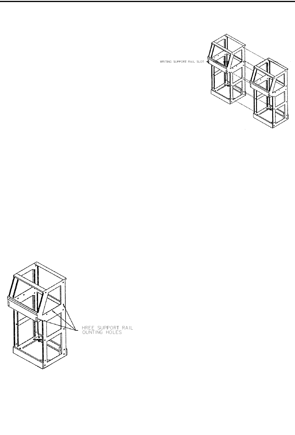
6. Using #1/4-20 x 3/4 hex bolts and #1/4-20 x 3/4
Keps nuts, attach the console sections together using
pass-through holes in the sides.
Note: Be consistent when orienting the bolts in the
pass-through holes. Refer to Figure 3-3.
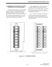
Do not attach the consoles at the centermost holes.
These holes will be used to fasten the writing sup-
port rails. Refer to Section 3.7.
7. Be sure the sections are in perfect alignment before
securing the fasteners.
HINT: When aligning console sections, a #2 Phil-
lips screwdriver may be placed through one of the
centermost holes and used as an alignment tool.
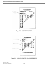
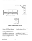
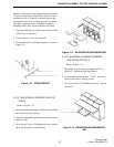
Figure 3-2 WRITING SUPPORT MOUNTING
HOLES
Figure 3-3 ASSEMBLY OF CONSOLE SEC-
TIONS
3.5 CONSOLE LEVELING
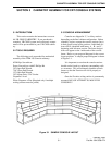
1. Consider carefully where the consoles are located.
Any gross unevenness in the flooring should be
eliminated. Small deviations can be compensated
using the individual levelers at each console.
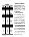
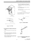
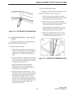
Note: Levelers are screwed in all the way in ship-
ment. Refer to Figure 3-5.
2. Level the console assembly both side-to-side and
front-to-back using the threaded levelers in each
cabinet section. Levelers can be adjusted by using
an 1/2" open end wrench or by hand turning. Hint:
a piece of scrap wood may be used to prop up the
console to aid in leveling. Be sure each leveler is
snug against the floor and supports its proper share
of the overall weight.
NOTE: Once the levelers have been extended, do
not shift the console position. Lateral movement
can bend the leveler stems making proper adjust-
ment extremely difficult.