


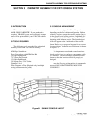

CABINETRY ASSEMBLY FOR CRT CONSOLE SYSTEMS
3-5
February 1996
Part No. 004-3039-274
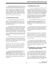
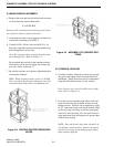
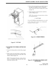
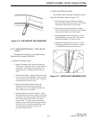
Figure 3-7 CTP TRAY
3.8 ATTACHING THE FORMICA WRITING SUR-
FACE
1. Position all writing surfaces on the writing support
rails.
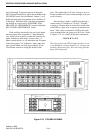
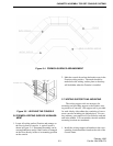
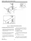
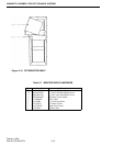
2. Where a split occurs in the Formica writing surface,
insert wood biscuits into the slots on the sides of the
surfaces. Refer to Figure 3-8.
HINT: To help align the Formica writing surfaces
flush, it is advisable to glue the biscuits into place
using white carpenter’s glue.
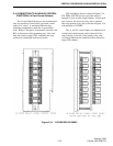
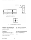
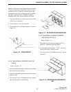
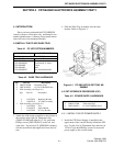
3. Pass the driver through the access in the bottom of
the support rail and drive #10x3/4" flakeboard
screws* up into the Formica writing surface. Refer
to Figure 3-9.
4. Align as necessary using an electric screwdriver
with a #2 Phillips driver.
NOTE: Hex extensions or long hex drivers will not
pass through the holes.
C A U T I O N
Use only VR-CM50-provided flakeboard screws to fas-
ten the writing surface. Longer screws will protrude
through the Formica surface.
Figure 3-8 JOINING FORMICA
Figure 3-9 SECURING THE FORMICA WRIT-
ING SURFACE