


CRT-BASED ELECTRONICS ASSEMBLY PART II
5-2
February 1996
Part No. 004-3039-274
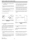
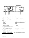
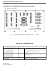
5.4 CONNECT THE CRT INTERFACE PROCESSOR (CIP) TRAY CABLES
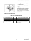
Refer to Figure 5-2 and Table 5-2.
Figure 5-2 CIP POWER SUPPLY LINE TERM BOARD - A1709230
Table 5-2 CRT CABLE CONNECTIONS
CIP Power Supply Line Term Board
(A1709230) Cable Conn
ections
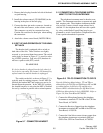
Footswitch Cable (A210906) Connect to Footswitch Jack
Red to AUX-FSPTT (TB11)
Green to AUX-FSMON (TB11)
Black to AUX-GND (TB11)
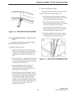
Mounts in the 5/8" hole at the base of the bay where the CIP
is installed. If there is no hole, provide one.
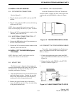
Power Fail Cable (A2109116) Connect to PC UPS (see Figure 5-1)
Green to AUX-AUX1 (TB11)
Red to AUX-AUX2 (TB11)
Black to AUX-GND (TB11)
POWER FAIL connector
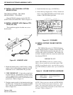
Console Serial Cable (A600991.6) Connect to PC CPU (see Figure 5-1)
P8 (CONSOLE) COM 3 (CIP Control Tray) connector