


CENTRAL PROCESSOR PACKAGE INSTALLATION
2-14
February 1996
Part No. 004-3039-274
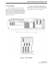
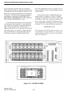
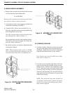
relays 9 through 16 mount at the top of the panel.
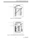
The Customer Data Sheets which are included in the
VR-CM50 Console Service Manual, Volume 1, will
define the relay panel assignments for all Auxiliary I/
O functions. Individual relay and input assignments
are defined in a report titled AUXILIARY CON-
TROL RELAY ASSIGNMENTS located behind the
RTL I/O PAIR ASSIGNMENTS sheets.
Each auxiliary function key has two logic inputs
and one output relay assigned to it. Input functions
vary widely from system to system but typically, the
inputs control key indications. In most cases, A
inputs control the left or off indication and B inputs
control the right or "on" indication. Inputs must be a
logic ground which can sink approximately 20 ma.
Use extreme caution in wiring the auxiliary func-
tions. The application of AC line voltage to an A or
B input terminal will cause serious damage to the pro-
cessor circuitry.
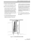
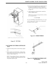
Each auxiliary output is a 4PDT relay having a
contact rating of 5 amperes at 120 VAC. If higher
voltages or currents must be controlled, use the relay
in the CPP as a pilot relay to operate an external con-
tactor. Each relay is mounted in a DIN socket with
screw terminals that can accept up to #12 wire. Refer
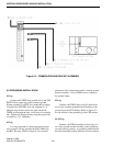
to Figure 2-13, for a detail of the relay connections.
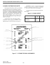
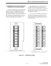
I M P O R T A N T
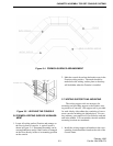
The relay panel in the CPP is hinged to allow access
to the backplane circuitry behind it. In wiring to the
auxiliary inputs and relays, dress all wiring from the
hinge side of the panel.
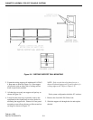
Figure 2-13 CPU RELAY PANEL