


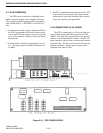

CABINETRY ASSEMBLY FOR CRT CONSOLE SYSTEMS
3-8
February 1996
Part No. 004-3039-274
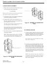
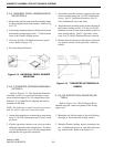
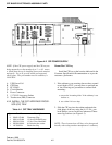
3.10.4 UNIVERSAL PENCIL DRAWER MOUNT-
ING (OPTION 4)
1. Remove the pencil drawer from the mounting frame
by depressing the black slide retainers. Refer to Fig-
ure 3-14.
2. Position the mounting frame in the desired location
between the writing support rails - 1 " back from the
front of the Formica writing surface.
3. Drive six (6) #10 x 3/4 flakeboard screws up into
wood. Refer to Figure 3-14
4. Re-insert the pencil drawer.
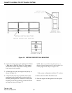
Figure 3-14 UNIVERSAL PENCIL DRAWER
MOUNTING
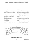
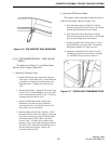
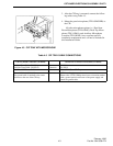
3.10.5 TYPEWRITER EXTENSION ASSEMBLY
(OPTION 5)
Refer to Figure 3-15. The Typewriter Extension
Assembly consists of a typewriter extension, a type-
writer extension support, two (2) triangle braces and
hardware. It is packed flat for shipping and must be
assembled in the field.
NOTE: The following assembly instructions pertain to
both 18" and 21" typewriter extension lengths.
1. Attach the triangle brace to the modesty panel using
three (3) 10-32x1/2 pan head screws for each trian-
gle brace.
2. Flip the typewriter extension over on its top side to
attach the other side of the triangle brace. Use three
(3) 10x3/4 flakeboard screws for each triangle brace
and attach to the typewriter extension.
3. Attach the typewriter extension support to the type-
writer extension using four (4) 10x3/4 flakeboard
screws. (On 21" typewriter extensions, five (5)
10x3/4 flakeboard screws are used).
4. Attach the entire assembly to the position desired on
the Formica writing surface. Use four (4) 10x3/4
flakeboard screws to secure the assembly to the For-
mica writing surface. (On 21" typewriter exten-
sions, five (5) 10x3/4 flakeboard screws are used).
5. Hand turn the leveling feet at the bottom of the mod-
esty panel to ensure a level typewriter extension
surface.
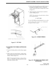
Figure 3-15 TYPEWRITER EXTENSION AS-
SEMBLY
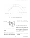
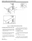
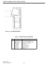
3.10.6 PIE SUPPORT RAIL MOUNTING (OP-
TION 6)
Refer to Figure 3-16. The Pie Support Rail is
attached using the same hole pattern as the writing
support rail.
1. Mount the rail with the angle of the rail following
the angle of the break in the writing surface.
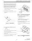
2. When the Formica writing surface is attached, use
two (2) flakeboard screws on each side of the writ-
ing surface break. Refer to the Section 3.5.