


CRT-BASED ELECTRONICS ASSEMBLY PART I
4-2
February 1996
Part No. 004-3039-274
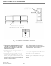
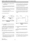
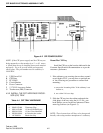
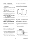
Figure 4-2 CIP POWER SUPPLY
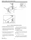
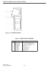
Mount The CIP Tray
Install the CIP tray at the location indicated in the
Customer Specifications Documentation or as per the
customer s preference.
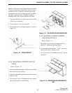
1. If the cabinetry you are using does not have a panel
reveal depth of 5/8", you may have to perform one
of the following two procedures to ensure flush
mounting :
a. remove the "mounting slides" if the cabinetry is too
shallow or,
b. use a shim if it is too deep.
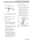
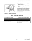
2. Slide the CIP tray into the cabinet and attach the
slide shims of the tray using the (4) 12-24x pan
head Phillips screws on the two innermost Tinner-
man clip positions (see Figure 4-3).
NOTE: These instructions will have to be interpreted
broadly when using another manufacturer’s cabinetry.
NOTE: If the CIP power-supply and the CIP tray are
being mounted over the monitor in a 5 or 10 turret,
a shield plate has to be installed between the monitor
and turret. Use a 16 ga cold rolled steel magnetic
shield plate. The part number used in cabinetry is
144113434.
A UPS Power Fail
B CPP Data
C PC COM3
D Circuit Breaker
E Power Connector
F 13.7V DC Accessory Outlets
G Touchscreen (DIN) Connector
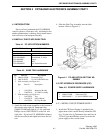
4.3.2 INSTALL THE CRT INTERFACE PROCE-
SOR (CIP) TRAY
Table 4-4 CIP TRAY HARDWARE
Qty Part No. Description
8
4
4
4
1
280621122400
280114122408
280129122416
280359120010
141230970A
Tinnerman Clips
12-24x1/2 PH Phil Screw
12-24x1 Truss Head Phil
#12 black nylon washer
Black trim strip