


CENTRAL PROCESSOR PACKAGE INSTALLATION
2-15
February 1996
Part No. 004-3039-274
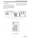
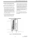
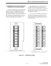
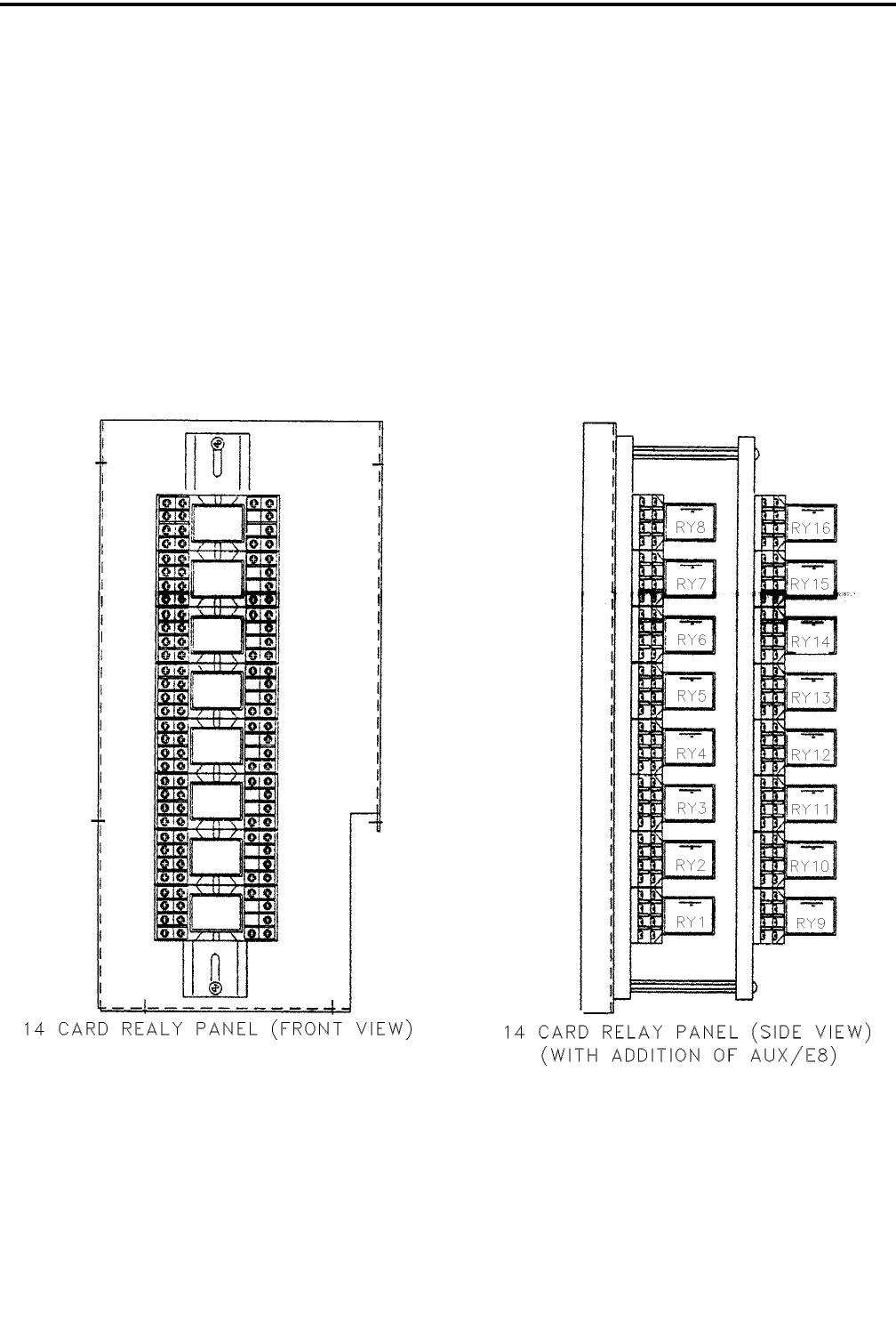
2.16 CONNECTION TO AUXILIARY CONTROL
FUNCTIONS (14 Card Central Cabinet)
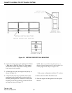
The 14 card Central Processor can accommodate
only one Auxiliary Control Relay card with a maxi-
mum of 16 relays. A somewhat different relay
mounting arrangement is used due to space limita-
tions. Relays 1 through 8 are mounted vertically with
RY1 at the bottom of the mounting strip. Note care-
fully the location of the COIL terminals; the relay
sockets are rotated 900 clockwise from the
CPU main Relay Panel as shown in Figure 2-14.
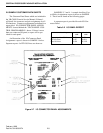
The TDM-AUX/E8 accessory provides relays 9
through 16, just as in the larger cabinets. In this pack-
age however, the accessory relay strip is stacked
above the primary relay strip as shown in Figure 2-14
with addition of AUX/E8.
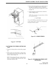
The A and B control inputs are contained on a
circuit board which mounts on the sidewall of the
relay housing to the left of the primary relay strip.
All control functions are identical to those shown for
larger CPP cabinets.
Figure 2-14 14 CARD RELAY PANEL