


4-1
February 1996
Part No. 004-3039-274
CRT-BASED ELECTRONICS ASSEMBLY PART I
SECTION 4 CRT-BASED ELECTRONICS ASSEMBLY PART I
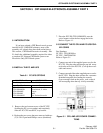
4.1 INTRODUCTION
Since you have purchased the E.F. JOHNSON
console system as electronics only and intend to use
another manufacturer s cabinetry, these install instruc-
tions will have to be interpreted broadly.
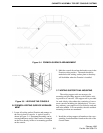
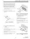
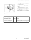
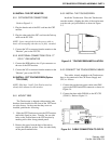
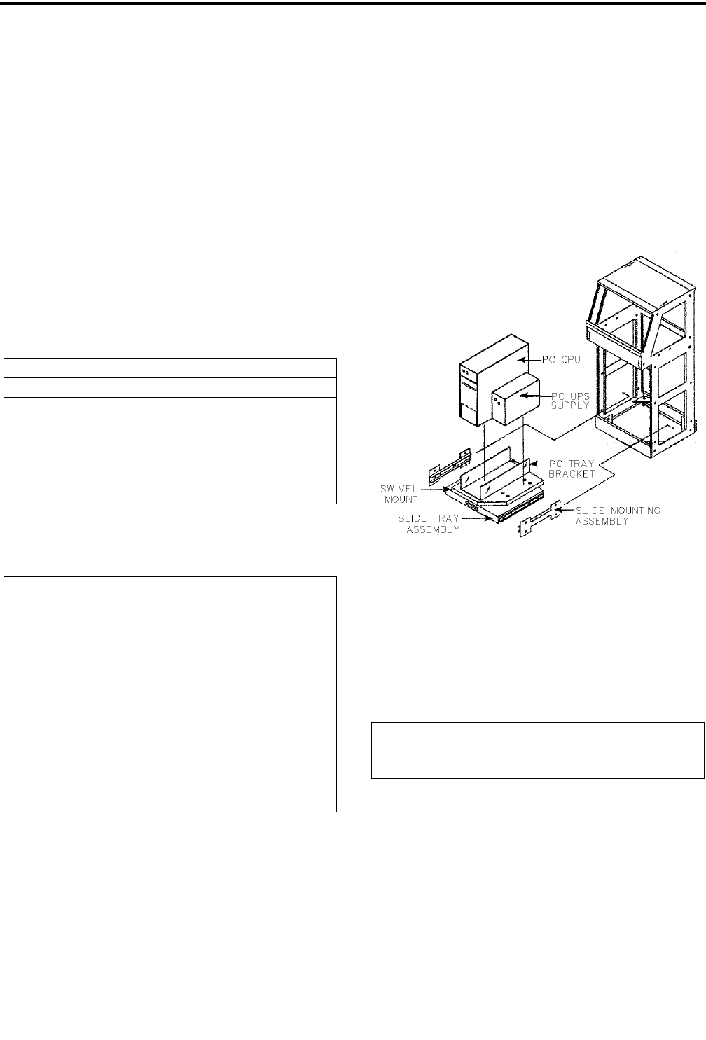
4.2 INSTALL THE PC/UPS SLIDE TRAY
3. Attach the slide mount assemblies to the bottom of
the console using eight (8) Tinnerman clips
(280621122400) and eight (8) 12-24x pan head
Phillips screws (280124102412) to the left and
right sides. If you have E.F. JOHNSON cabinetry,
use the second hole and eighth hole from the bot-
tom.
4. Slide the Slide Tray Assembly onto the slide
mounts. Refer to Figure 4-1.
Figure 4-1 PC AND UPS SLIDE TRAY AS-
SEMBLY
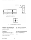
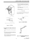
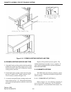
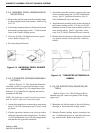
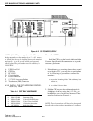
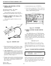
4.3 CRT INTERFACE PROCESSOR (CIP)
4.3.1 INSTALL THE CIP POWER SUPPLY
1. Install the CIP Power Supply is installed in the
upper turret of the console directly behind the CIP
tray. Use the four (4) Tinnerman clips and four (4)
12-24x1/2 pan head Phillips screws to secure the
power supply to the console frame.
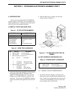
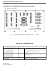
Table 4-1 PC UPS OPTION NUMBERS
PC CPU Part No. 200TC4862501
Possible option numbers for the PC UPS
Part Number Country
TDV-OP400/A
TDV-OP400/GB
TDV-OP400/E
TDV-OP400/I
TDV-OP400/NZ
North America
Great Britain, S. Africa
Europe
India
New Zealand/Australia
Table 4-2 SLIDE TRAY HARDWARE
Qty Part No. Description
8
8
280621122400
280124102412
Tinnerman Clips
12-24x1/2 PH Phil Screw
2 Slide Assembly (see Figure 4-1)
Qty.
2
2
Part No.
144233259
146563216
Description
Mounting Bracket
16" Slide Assembly
1 Slide Assembly (see Figure 4-1)
1
1
1
144233258
124163270
144233386
Tray
Swivel Mount
PC Tray Bracket
Table 4-3 POWER SUPPLY HARDWARE
Qty Part No. Description
4
4
280621122400
280124102412
Tinnerman Clips
12-24x1/2 PH Phil Screw