


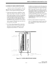
CENTRAL PROCESSOR PACKAGE INSTALLATION
2-8
February 1996
Part No. 004-3039-274
2.8 SAMPLE CUSTOMER DATA SHEETS
The Customer Data Sheets which are included in
the VR-CM50 Console Service Manual, Volume 1,
will detail the connector and pair assignments for all
I/O functions. Connector assignments are defined in a
report titled I/O CONNECTOR PANEL ASSIGN-
MENTS located behind the T/R CHANNEL CON-
TROL PROGRAMMING sheets. If there is more
than one connector I/O panel, a report will be pro-
vided for each panel.
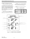
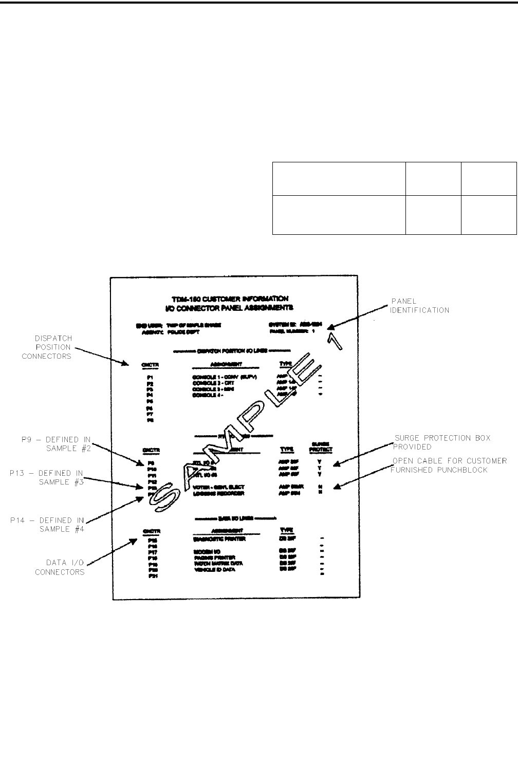
An illustration of the I/O Connector Panel
Assignments report is shown in SAMPLE 1 below.
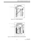
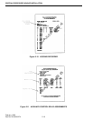
Separate reports for RTL I/O Lines are shown as
SAMPLES 2, 3 and 4. A sample Auxiliary Con-
trol Relay Assignments report is shown as SAMPLE
5. These can be found on the following pages.
A separate report is provided for each I/O Con-
nector Panel.
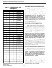
Table 2-2 I/O PANEL REPORT
I/O Conn. Panel Report 14 Card
CPP
20+ Card
CPP
Dispatch position I/O Lines
RTL I/O Lines
Data I/O Lines
P1-P3
P4-P7
P8-P11
P1-P8
P9-P14
P15-P21
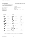
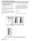
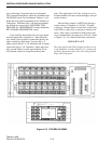
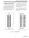
Figure 2-7 I/O CONNECTOR PANEL ASSIGNMENTS