


CRT-BASED ELECTRONICS ASSEMBLY PART I
4-3
February 1996
Part No. 004-3039-274
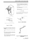
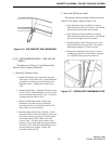
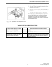
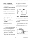
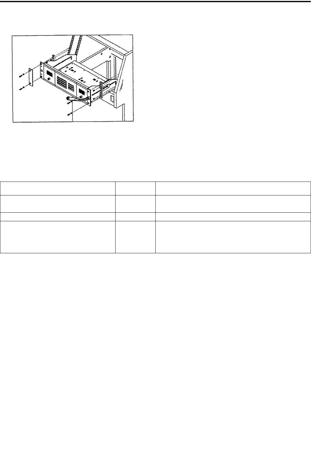
Figure 4-3 CIP TRAY WITH MICROPHONE
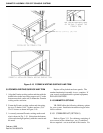
3. After the CIP tray is mounted, connect the follow-
ing cables using Table 4-5.
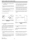
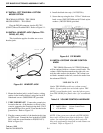
4. Mount the panel microphone (TDV-OP402/HR) to
the CIP:
All other microphone options, i.e., Dual Arm
Boom Microphone (TDV-OP403), Desk-Top Micro-
phone (TDV- OP404), and Auxiliary Microphone
Location (TDV-OP405), have customer specific
installation requirements and will not be included in
this Installation Guide.
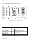
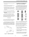
Table 4-5 CIP TRAY CABLE CONNECTIONS
CIP Tray Board Connections (A1709228) CIP PS Line Term Board Connections (A1709230)
1st Line Term Cable - P9 (I/O 1) Connect to P1 (I/O 1)
2nd Line Term Cable - P6 (I/O 2) Connect to P1 (I/O 2)
Red/Black CIP Power Cable Connect to P2 (13.7V DC) on CIP Tray
Ground Cable (A600966.18) Connect to CIP Power Supply
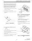
The ground cable is attached to the center
Pem nut on the rear of the CIP tray.
Remove the 5-32x1/2 Philips head screw at location marked
with a ground symbol on the rear of the power supply and
attach the ground cable.