


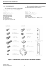
CENTRAL PROCESSOR PACKAGE INSTALLATION
2-3
February 1996
Part No. 004-3039-274
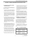
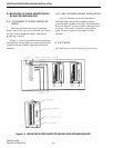
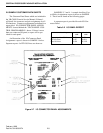
2.3 CONNECTION OF THE CENTRAL PRO-
CESSOR PACKAGE CABLES
When multiple CPP cabinets are reuired, the sys-
tem layout will have been designed to minimize the
cabling needed between cabinets. At minimum, it will
be necessary to connect the ribon cables from the
Inter-Cabinet Repeater (ICR) cards in the first cabinet,
to the backplanes and power supplies in the expan-
sion cabinets. Depending on the size of the CPP, the
cables are marked with either RED DOTS or GREEN
DOTS.
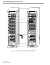
Connect the cables marked with a RED dot to the
Line Terminator Board, which is also marked with a
RED dot. Perform the same procedure if the cables
are marked with GREEN dots (see Figure 2-2.
In some cases, it may be necessary to connect I/O
ribbon cables or intercabinet mute wiring. Instruc-
tions for these details are unique to each system and
will be found in a document titled "Installation Notes"
at the front of the "Customer Data" Section in in Vol-
ume 1 of the VR-CM50 Console Service Manual.
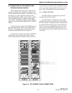
2.3.1 CABLE ROUTING
60" CPP cabinets are designed for cable feed
from the bottom of the cabinet.
80" CPP cabinets are designed to accept cable
feeds from either the top or the bottom of the cabinet.
88" CPP cabinets are shipped with the assumption that
the cables will feed from the top or from beneath the
floor. If cable access through the bottom rear cowl is
desired, remove the black hole plugs from the cowl
and exchange them with the cable bushings in the top
vent panel.
Figure 2-2 CPU CABINET CABLE CONNECTIONS