


Part number 550-142-054/0411
GV90+ gas-fired water boiler — Boiler Manual
8
Prepare the boiler (continued)
Check orifice plate — replace if necessary
The correct orifice plate must be used. Failure to do so
will result in severe personal injury, death or substantial
property damage. The boiler is shipped with a natural
gas orifice plate. It MUST BE CONVERTED to use
propane.
Natural gas:
For natural gas installations, inspect the silver gas/air orifice plate
marking
. It must be the same as the boiler size. If the orifice plate is
stamped with another size, obtain the correct plate from your whole-
saler. The boiler size is stamped where the “X” is shown in the plate
stamping, Figure 6.
Propane:
For propane installations, replace the silver gas/air orifice plate
with the red/white plate
, per following instructions. Ensure the red/
white plate boiler size is correct for the GV90+ boiler being installed.
The boiler size is stamped where the “X” is shown in the plate stamp-
ing, Figure 6.
Also fill out the propane label in the conversion kit and attach to the
left side of the jacket, above the gas inlet opening, as shown in Figure 5.
Orifice plate installation, when required
Access the bottom of the blower housing as shown in Figure 5.
To inspect the plate only,
read the marking on the plate edge. It
must read the same as the boiler size and fuel, as follows:
Boiler model Natural gas marking Propane marking
GV90+3 NG 3 SEC LP 3 SEC
GV90+4 NG 4 SEC LP 4 SEC
GV90+5 NG 5 SEC LP 5 SEC
GV90+6 NG 6 SEC LP 6 SEC
To replace the plate, using a manual screwdriver or nut driver, see
Figure 6:
1. Loosen screws
1 and 2 two full turns.
2. Remove screws
3 and 4.
3. Pull the gas/air orifice plate forward to remove it.
4. Slide in the new plate as shown in Figure 6. The
red side of a
propane plate must go next to the blower housing
.
5. Replace screws
3 and 4. Tighten all four screws securely and uni-
formly. DO NOT overtighten. DO NOT exceed 40 inch-pounds
torque.
6. Bend down plate label tab at score mark as shown in lower right
corner of Figure 6, item 10.
DO NOT use electric or pneumatic screwdrivers to re-
move or tighten the gas/air boss screws. Hand-tighten
only, using manual screwdriver. Should the torque exceed
40 inch-pounds, the threaded holes could strip out,
causing an inadequate seal of the orifice plate. Failure to
properly seal the plate to the housing could result in a gas
leak, causing severe personal injury, death or substantial
property damage.
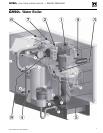
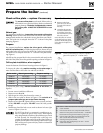
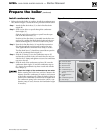
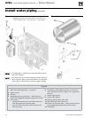
Figure 5 Check for correct gas orifice plate
A Remove jacket front
panel to access the bot-
tom side of the blower
housing.
B Complete the propane
conversion label includ-
ed with the conversion
kit. Install label on jacket
left side, as shown.
Leave the boiler on its back,
on the skid as shown, until
you have checked the gas/air
orifice plate and replace it if
necessary.
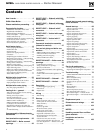
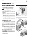
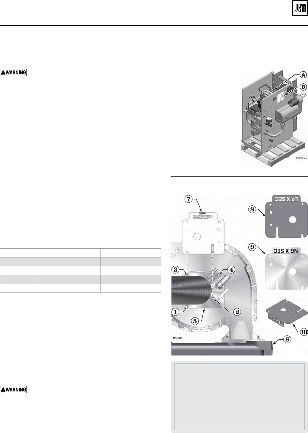
Figure 6 Follow instructions to check or replace
gas orifice plate ("X" = boiler size)
1–4 Screws — follow instructions for loosening and tightening
5 Gas/air manifold
6 Front section, bottom view, component details omitted
7 Side shown must point toward air inlet hose — WARNING
label side for natural gas; WHITE side for propane gas
8 Propane orifice plate, RED one side and WHITE on the
other (red side must face the blower housing
9 Natural gas orifice plate, SILVER
10 Orifice plate after bending along score mark — label is
visible when installed