


Part number 550-142-054/0411
GV90+ gas-fired water boiler — Boiler Manual
54
Gas piping
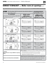
Connecting gas supply piping
Do not connect gas supply to boiler or at-
tempt to operate boiler unless the correct
orifice plate has been verified or installed
in accordance with page 8.
Except where otherwise instructed in
this manual, do not attempt to measure
or adjust the outlet pressure setting of
the gas valve.
The gas valve is factory
set to a slight negative pressure, and is
operated as a negative-pressure regulated
valve.
Failure to comply will result in malfunc-
tion of the boiler, causing severe personal
injury, death or substantial property
damage.
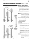
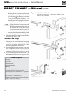
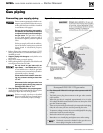
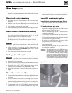
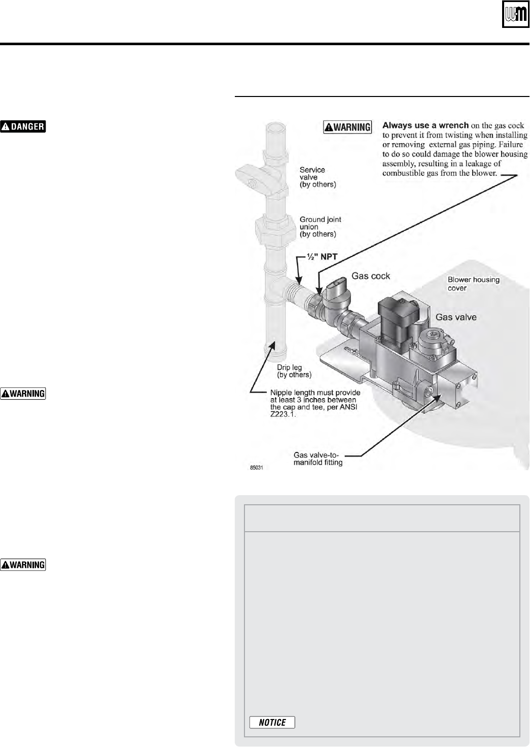
1. Refer to Figure 64 to connect gas supply to ½” NPT
boiler gas connection. Use wrench to hold factory-
installed gas cock.
2. Support piping with hangers, not by boiler or its
accessories.
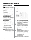
3. Purge all air from gas supply piping.
4. Before placing boiler in operation, check boiler and
test all gas connections for leaks.
Do not check for gas leaks with an
open flame
— use bubble test. Failure
to use bubble test or check for gas leaks
can cause severe personal injury, death or
substantial property damage.
Close manual main shutoff valve dur-
ing any pressure testing at less than
13” w.c.
Disconnect boiler and gas valve from
gas supply piping during any pressure
testing greater than 13” w.c.
5. Use pipe dope compatible with propane gases.
Apply sparingly only to male threads of pipe joints
so that pipe dope does not block gas flow.
Failure to apply pipe dope as detailed
above can result in severe personal injury,
death or substantial property damage.
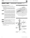
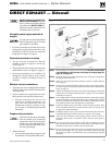
Figure 64 Gas supply connection to GV90+ boiler gas manifold
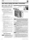
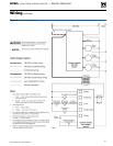
Honeywell VK8115V-1176 gas valve
• The Honeywell VK8115V-1176 gas valve operates with DC
voltage.
• The black power plug that connects to the gas valve contains
a DC rectifier.
• When the gas valve is energized, approximately 19 to 21 volts
DC voltage should be measured across the two outer pins of the
gas valve connector plug.
• There are 4 pins on the gas valve and 3 pin receptacles in the plug.
Only the two outer pins are used for powering the valve.
• To measure voltage, remove the screw and slightly lift the plug
until meter leads can touch end pins.
• Run boiler and test for proper voltage.
• Remember to re-install plug and tighten screw after testing.
Continuity cannot be checked in the gas valve con-
nector plug wiring due to the rectifier.