


Part number 550-142-054/0411
63
GV90+ gas-fired water boiler — Boiler Manual
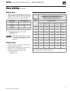
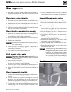
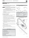
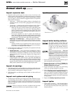
Figure 73 Tools required for gas valve outlet
pressure measurement
1 U-tube manometer with tubing -
Manometer provides a fine scale by
slanting the manometer (Dwyer Model
1227 recommended).
2 Tee hose fitting (provided in high
altitude kit).
3
1
/16" flat head screw-
driver.
4 T-40 star drive for
gas valve pressure
regulator cover
screw.
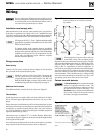
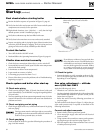
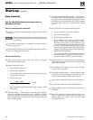
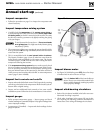
Figure 74 Carefully connect manometer to gas valve
as shown, following instructions on this
page (see legend at left)
5. Position and zero manometer per manufacturer’s instructions. The
manometer must have at least 6” of tubing above the fluid level or
fluid may be drawn into the gas valve.
If manometer fluid is drawn into gas valve body, gas valve
must be replaced. Fluid in valve will cause it to malfunc-
tion, possibly resulting in severe personal injury, death
or substantial property damage.
6. Disconnect tube from hose barb on gas valve vent tap. Connect
tube end to tee hose fitting as shown in Figure 74. Then add length
of hose from tee hose fitting to gas valve vent tap.
7. Connect positive side manometer hose to top of the tee hose fit-
ting (Figure 74).
8. Connect negative side manometer hose to the barrel of the gas
valve outlet pressure tap (Figure 74).
Check gas valve setpoint
1. Open manual gas valve and turn on electrical power to boiler.
2. Start boiler and allow boiler to run for 5 minutes.
3. Read manometer. This is the gas valve outlet pressure set point. If
set point is between – 0.1” w.c. and – 0.3” w.c. go to step 7.
4. If gas valve setpoint is not between – 0.1” w.c. and – 0.3” w.c., use
T-40 driver to remove cap on gas valve pressure regulator.
5. Turn gas valve pressure regulator screw counter clockwise
to
lower gas valve set point to – 0.2” w.c.
6. Reinstall cap on gas valve pressure regulator using T-40 driver.
7. Cycle boiler off and on several times to verify gas valve set point.
If set point does not remain between - 0.1” w.c. and – 0.3” w.c.,
readjust as necessary.
8. Close manual gas supply valve and turn off electrical power to
boiler.
9. Remove manometer hose from gas valve outlet pressure tap barrel
and replace sealing screw.
10. Remove tee hose fitting and added tube.
11. Reinstall hose on gas valve vent tap hose barb.
12. Open manual gas supply valve and turn on electrical power to
boiler.
Legend for Figure 74
1 Gas control outlet pressure tap — located on back side of gas control. Use tap
closest to gas control gas outlet —Remove screw from gas control outlet pressure
tap and slide hose over tap
2 Add tee hose fitting as shown
3 Existing hose to gas control vent tap hose barb — Remove from gas control vent
tap and connect to end of tee as shown
4 Gas control pressure regulator cap
5 Honeywell Type VK8115V gas valve
6 Gas outlet vent tap
7 Gas outlet piping
8 Add hose from gas control vent tap to tee hose fitting
Start-up (continued)