


Part number 550-142-054/0411
61
GV90+ gas-fired water boiler — Boiler Manual
Start-up (continued)
3. Inject all of the inhibitor supplied with the boiler. Allow time for
the water to circulate and mix. Then check the inhibitor level. Add
additional inhibitor if necessary.
Check/verify water chemistry
1. The system may have residual substances that could affect water
chemistry.
2. After the system has been filled and leak tested, verify water pH
and chlorine concentrations are acceptable.
3. Verify antifreeze concentration, when used.
4. Follow the instructions on the Sentinel test kit to sample the system
water and verify inhibitor concentration.
Check inhibitor concentration annually
1. Test the pH of a sample of system water at least annually. The pH
of the water mixture must be between 7.0 and 8.5. (Or use the
Sentinel inhibitor test kit to check concentration.)
2. If pH is outside this range (or inhibitor test kit indicates low level),
the inhibitor level may not be sufficient to prevent corrosion.
3. Test antifreeze concentration.
Test antifreeze concentration at least annually. If concen-
tration is low, add antifreeze or drain system and refill
with correct mixture.
4. Follow instructions on antifreeze container to determine the
amount of antifreeze needed.
DO NOT exceed 50% by volume
concentration of antifreeze.
5. Check inhibitor level after adjustments are made.
Verify gas/air orifice plate
The proper orifice plate must be used. Failure to do
so will cause severe personal injury, death or substantial
property damage.
1. Remove the jacket front panel.
2. Read the boiler size written on the gas/air orifice label tab, verifying
the correct size. See Figure 5, page 8 for details.
3. The orifice plate must be plain aluminum for natural gas. For
propane gas, the exposed tab of the plate should be red.
4. Replace the orifice plate if necessary, following the guidelines on
page 8.
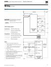
Check thermostat circuit(s)
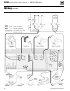
1. Disconnect the two external wires connected to the boiler thermo-
stat terminals (see Field wiring, beginning on page 56 for terminal
locations).
2. Connect a voltmeter across these two incoming wires. Close each
thermostat, zone valve and relay in the external circuit one at a
time and check the voltmeter reading across the incoming wires.
3. There should NEVER be a voltage reading.
4. If a voltage does occur under any condition, check and correct the
external wiring. (This is a common problem when using 3-wire
zone valves.)
5. Once the external thermostat circuit wiring is checked
and corrected if necessary, reconnect the external ther-
mostat circuit wires. Allow the boiler to cycle.
Inspect/fill condensate system
Inspect/check condensate lines and fittings
1. Inspect the condensate drain line, condensate PVC fit-
tings and condensate trap.
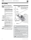
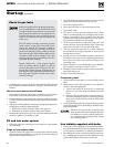
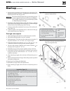
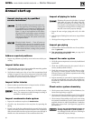
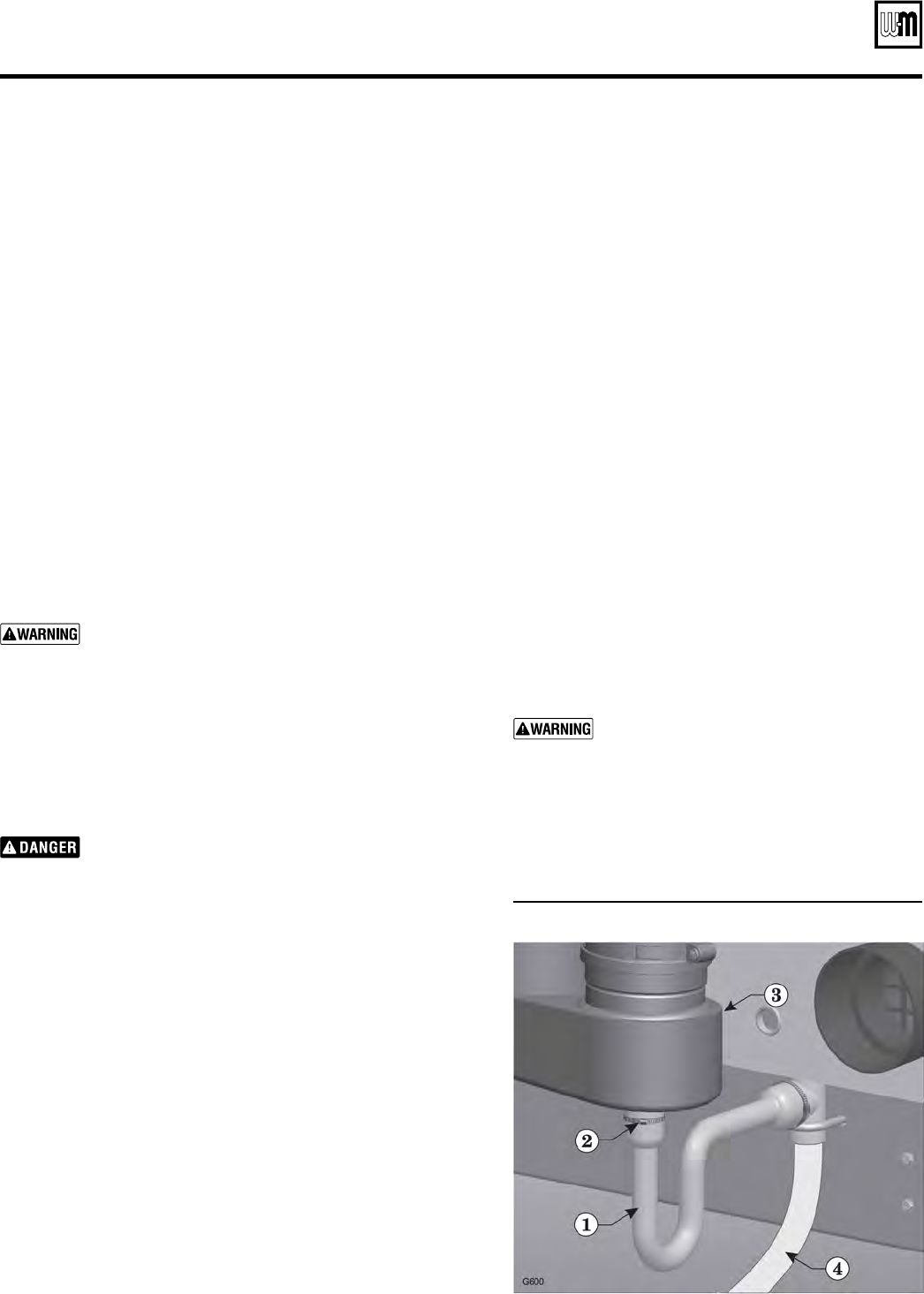
Fill condensate trap with water
1. Loosen the hose clamp (Figure 70, item 2) that secures
the condensate trap (Figure 70, item 1) to the bottom
of the recuperator (Figure 70, item 3).
2. Pull the condensate trap tube off of the recuperator
condensate drain nipple.
3. Use a funnel to feed water into the top of the conden-
sate tube.
4. Continue filling until water begins to flow out through
the condensate line (Figure 70, item 4).
5. Re-attach the condensate trap to the bottom of the
recuperator. Secure with the hose clamp.
6. Check for any leaks in the condensate drain line or fit-
tings. Repair any leaks.
7. Remove the temporary clamp (see step 2, above) from
the condensate drain tube.
The condensate trap must be filled with water
during all times of boiler operation to avoid
flue gas emission from the condensate drain
line. Prime the condensate trap by pouring
water into the outlet tee while restricting flow
in drain tube if boiler has been out of service
for an extended period. Failure to fill the trap
could result in severe personal injury or death.
Figure 70 Condensate trap assembly