


Part number 550-142-054/0411
GV90+ gas-fired water boiler — Boiler Manual
16
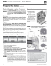
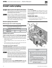
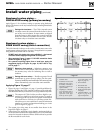
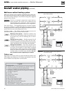
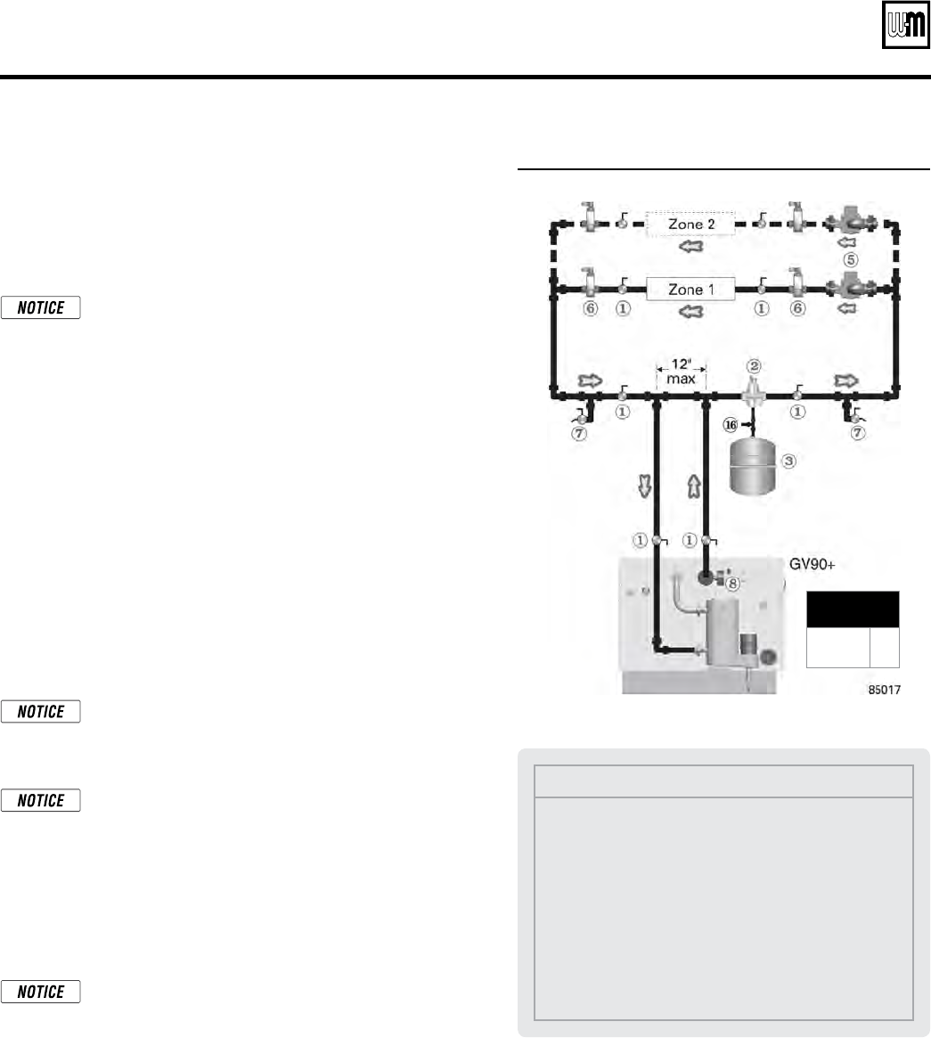
Figure 17 Baseboard system — circulator zoning
Baseboard system piping —
CIRCULATOR zoning (primary/secondary)
Apply Figure 17 for circulator zoning on systems using baseboard
heaters. The heaters can be any baseboard style, including finned tube
or cast iron.
Zoning with circulators — The GV90+ internal system
circulator cannot be removed from the boiler for use as
one of the zone circulators. It must remain as shipped
from the factory to allow proper flow control inside the
boiler. You will need a circulator for each zone. Provide
circulator relays or circulator zone controller.
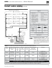
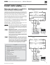
Baseboard system piping —
ZONE VALVE zoning (direct connection)
The boiler internal circulator can be used to circulate many zone-valve
zoned systems as shown in Figure 18, page 17 for application on systems
using baseboard (finned tube or cast iron).
• DO NOT apply this piping when using a GV90+6 — the internal
circulator cannot supply enough flow to the system
.
• When applying Figure 18, page 17, DO NOT exceed the limits
shown in Figure 19, page 17
.
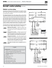
• For systems requiring higher flow or head loss, apply the
suggested piping of Figure 20, page 18, NOT that of Fig-
ure 18, page 17.
Balancing, when required
—
Substitute a memory-stop
valve for one of the isolation valves in each zone to use
the memory-stop valve for balancing flow as well as
isolation.
Zoning with zone valves —
Provide a separate 24-volt
transformer to power the zone valves. Size the trans-
former to handle the total rated load of all connected zone
valves. Alternatively, use a zone valve zone controller.
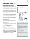
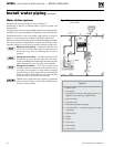
Applying Figure 18, page 17
1. Figure 18, page 17 and Figure 19, page 17 provide guidelines for
checking whether the GV90+ internal circulator can provide suffi-
cient flow when directly connected to a two-pipe baseboard system.
The outputs of GV90+ boilers are all too high for con-
nection to a single-loop series-loop system. To apply to
an existing series loop system, the system must be fitted
with trunk lines to convert to a split-loop system. Pro-
vide either one or two trunk lines to meet the minimum
number of circuites and maximum loading per circuit
given in Figure 19, page 17.
2. The system pipe sizing must be no smaller than shown in the
Legend for Figure 18, page 17.
3. Values shown for maximum circuit lengths, maximum load per
circuit and the maximum feet baseboard per circuit are limits that
ensure the internal circulator will have sufficient head to provide
the flow needed for each circuit.
MINIMUM
Boiler loop pipe size
GV90+3/4
GV90+5/6
1”
1¼”
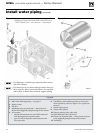
Legend
1 Isolation valves
2 Automatic air vent (with
diaphragm-type expan-
sion tank), or connect to
tank fitting (closed-type
expansion tank).
3 Diaphragm- or bladder-
type expansion tank, if
used. (For closed-type
expansion tank, pipe
from top of air separa-
tor to tank fitting as in
Figure 15, page 14.)
5 Zone circulator
6 Flow/check valve
7 Hose bibb purge valve
8 Boiler pressure/tempera-
ture gauge
16 Cold water fill line — see
Figure 15, page 14 for
typical components
Install water piping (continued)