


Part number 550-142-054/0411
GV90+ gas-fired water boiler — Boiler Manual
74
Removing/cleaning/re-installing the recuperator
Disconnect the vent pipe from the recuperator
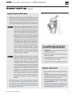
1. The vent pipe must be disconnected (at the in-line flue drain, item
A in Figure 7, page 9).
2. If the vent piping can be moved enough, loosen the flue pipe clamp
on the in-line flue drain. Then lift the flue pipe up and move aside
slightly.
3. If the vent piping cannot be moved, then cut the flue pipe carefully
so a coupling can be inserted later, or remove a section of vent pipe
if using stainless vent pipe.
Isolate boiler and drain partially
1. Remove the jacket top panel and front panel.
2. Allow time for the boiler to cool down if it has been operating.
3. Close the isolation valves on the boiler supply and return con-
nections.
4. The boiler will have to be partially drained.
a. Place a large pan under the boiler drain valve.
b. Slowly open the drain valve and allow about a gallon of water
to drain out.
c. Place the pan under the water connection flanges on the re-
cuperator.
d. Loosen the upper recuperator flange and allow any water in
the line to run out.
e. Loosen the lower recuperator flange (return connection) and
allow the water in the line and recuperator to drain out.
5. After the recuperator and water lines have been drained, disconnect
both recuperator flanges.
Remove the recuperator
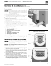
1. See Figure 102, page 95. Loosen the (4) nuts that secure the recu-
perator to the boiler.
2. Carefully slide the recuperator off of the (4) studs.
3. Disconnect the plug-in connector on the thermal fuse (Fig-
ure 102, page 95, item 27).
4. Loosen the flue adapter clamp and remove the in-line drain fitting
from the flue adapter.
5. Dump any remaining water from the recuperator.
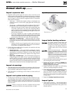
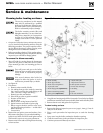
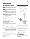
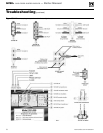
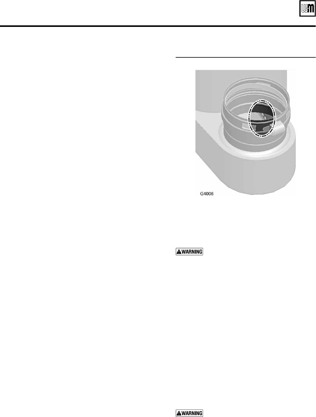
6. Look through the flue adapter and locate the flueway drain holes
as shown in Figure 84.
7. Use a brush or other means to remove blockage from these
holes.
8. Rinse the recuperator thoroughly.
Re-install the recuperator
1. Inspect the recuperator gaskets to make sure all are in good condi-
tion. Replace if there is any sign of damage.
2. Attach the recuperator at the boiler connection.
3. Secure with the four nuts.
4. Re-connect the water connections to the upper and lower recu-
perator flanges.
5. Re-insert the in-line drain fitting into the recuperator vent adapter.
Tighten the clamp to secure in place.
6. Re-connect the plug-in connector on the thermal fuse (Fig-
ure 102, page 95, item 27).
Figure 84 Recuperator flueway drain holes
Service & maintenance (continued)
Re-install the condensate trap and recuperator ac-
cess cover
1. Replace the condensate trap and recuperator access
cover — tighten bolts securely (do not exceed 18 inch-
pounds, 2 N-m, torque).
If the recuperator shows signs of significant
corrosion or deterioration, contact Weil-
McLain for recommendations on investigat-
ing the cause and replacing the recuperator if
necessary.
Make sure the recuperator access cover gasket
is in good condition. Replace if necessary.
Make sure the recuperator access cover and
the condensate trap are re-installed securely.
Failure to comply with the above could result
in severe personal injury, death or substantial
property damage.
Re-connect the vent pipe
1. If the vent pipe was lifted out, re-insert the vent pipe
into.
2. If the vent pipe was cut, install a coupling in the vent
line to allow re-connection.
3. If a section was removed (stainless vent pipe), replace
the section.
4. Re-connect the vent pipe to the in-line drain fitting and
tighten the clamp.
When replacing the vent pipe, follow all in-
structions in this manual to ensure the vent
is properly completed. Failure to properly the
vent pipe could result in severe personal in-
jury, death or substantial property damage.