


Part number 550-142-054/0411
15
GV90+ gas-fired water boiler — Boiler Manual
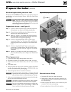
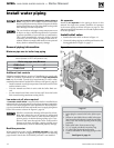
Install water piping (continued)
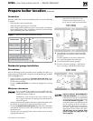
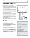
System water piping methods
Most piping methods shown in this manual use
primary/secondary connection to the boiler loop.
These designs ensure proper flow through the
GV90+ boiler, for the most efficient and reliable
operation of the boiler and the heating system.
For other piping methods, consult your local Weil-
McLain representative.
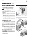
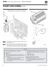
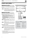
Circulators
Do not remove either of the GV90+ internal pumps
for use elsewhere in the system. Both pumps are
required for proper operation. Removing a pump
will cause the boiler to malfunction. Substantial
property damage could result.
Never install another pump in series with the
GV90+ boiler
. Forced flow can cause improper op-
eration of the boiler controls. Substantial property
damage could result.
Failure to comply could result in unreliable perfor-
mance and nuisance shutdowns from insufficient
flow.
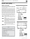
Circulator flow rate
Size system circulators based on the flow rate required to achieve
the temperature change needed. You can closely estimate tem-
perature rise (or drop) through a circuit by using the following
formula, where TD is temperature rise (or drop), FLOW is flow
rate (in gpm), and BTUH is the heat load for the circuit:
FLOW =
BTUH
—–—–—–—–
TD x 500
Examples:
Consider a system loop for a system with total heating load equal
to 210,000 Btuh. The desired temperature drop through the system
piping is 20°F. Then the required flow rate is:
FLOW =
210,000
—–—–—–—–
20 x 500
= 21 gpm
SIMPLIFIED: For 20° temperature drop, FLOW = MBH / 10.
Circulator head requirement
The circulator must be capable of delivering the required flow
against the head loss that will occur in the piping. Determine
the pipe size needed and the resultant head loss using accepted
engineering methods. The simplified pipe sizing here is limited
to residential systems, and does not include systems with fan coil
units or radiant tubing.
The following simplified method for pipe and cir-
culator sizing must be limited to residential applica-
tions using baseboard (finned or cast iron), cast iron
radiators or convectors. DO NOT apply for radiant
heating, fan coil units or commercial installations.
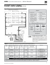
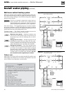
Simplified pipe/circulator selection
1. Install the boiler and piping using the recommended piping
layouts in this manual.
2. Size the piping and components for each circuit in the space
heating system using Figure 16.
At the flow rates listed, the
head loss in all piping will be 0.04 feet per foot of pipe.
a. Determine the heating load (Btuh) for each circuit.
b. Calculate the flow rate for each circuit using its load.
To use a 20°F temperature drop, just divide the
MBH (1,000’s of Btuh) by 10.
Example — Flow for 20°F temp drop with 35,000
Btuh:
FLOW = 35 MBH / 10 = 3.5 gpm
c. Find the pipe size in Figure 16 that has a max flow rate
just larger than that required for the circuit.
d. Find the total equivalent length (TEL) of the circuit.
TEL accounts for losses through fittings and valves by
using the equivalent length of pipe that would cause
the same head loss. Add these numbers to the measured
length of the circuit to find TEL in feet.
TEL is usually close to 1.5 times the length of the
circuit for residential baseboard, radiator or convec-
tor applications.
e. Measure the length of each circuit from the circulator
outlet back to its inlet. Then multiply this length times
1.5 to get the approximate TEL of the circuit.
f. Find the head loss for each circuit:
TEL = 1.5 X Circuit Length (feet)
HEAD = TEL X 0.04 (feet water column)
g. NOTE: Size system header piping for the total flow of
all connected zones.
3. Example:
a. For a circuit with heating load = 45,000 Btuh (= 45
MBH). Measured length of circuit is 88 feet.
b. Flow = 45 MBH / 10 = 4.5 gpm.
c. TEL = 1.5 x 88 feet = 132 feet.
d. From Figure 16, select 1" pipe (max flow = 8 gpm).
e. Head loss = TEL x 0.04 = 132 x 0.04 = 5.28 feet.
f. Select a circulator that can deliver at least 4.5 gpm at a
head of 5.28 feet. (Read the NOTICE below.)
To use this method, limit the flow through ¾"
finned-tube baseboard to 3.9 gpm, or use 1" base-
board and limit flow to 7.1 gpm. If the total load
of the circuit requires more flow, split the circuit
into two or more.
Figure 16
Flow rates for 0.04 feet head loss per foot of
copper pipe
(based on water at140°F)
Pipe size
(inches)
MAX Flow rate (GPM)
@ 0.04 feet per foot
Pipe size
(inches)
MAX Flow rate (GPM)
@ 0.04 feet per foot
¾
4
2
45
1
8
2½
75
1¼
14
3
140
1½
22
4
290