


Part number 550-142-054/0411
GV90+ gas-fired water boiler — Boiler Manual
72
Service & maintenance
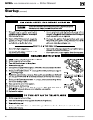
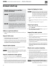
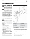
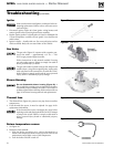
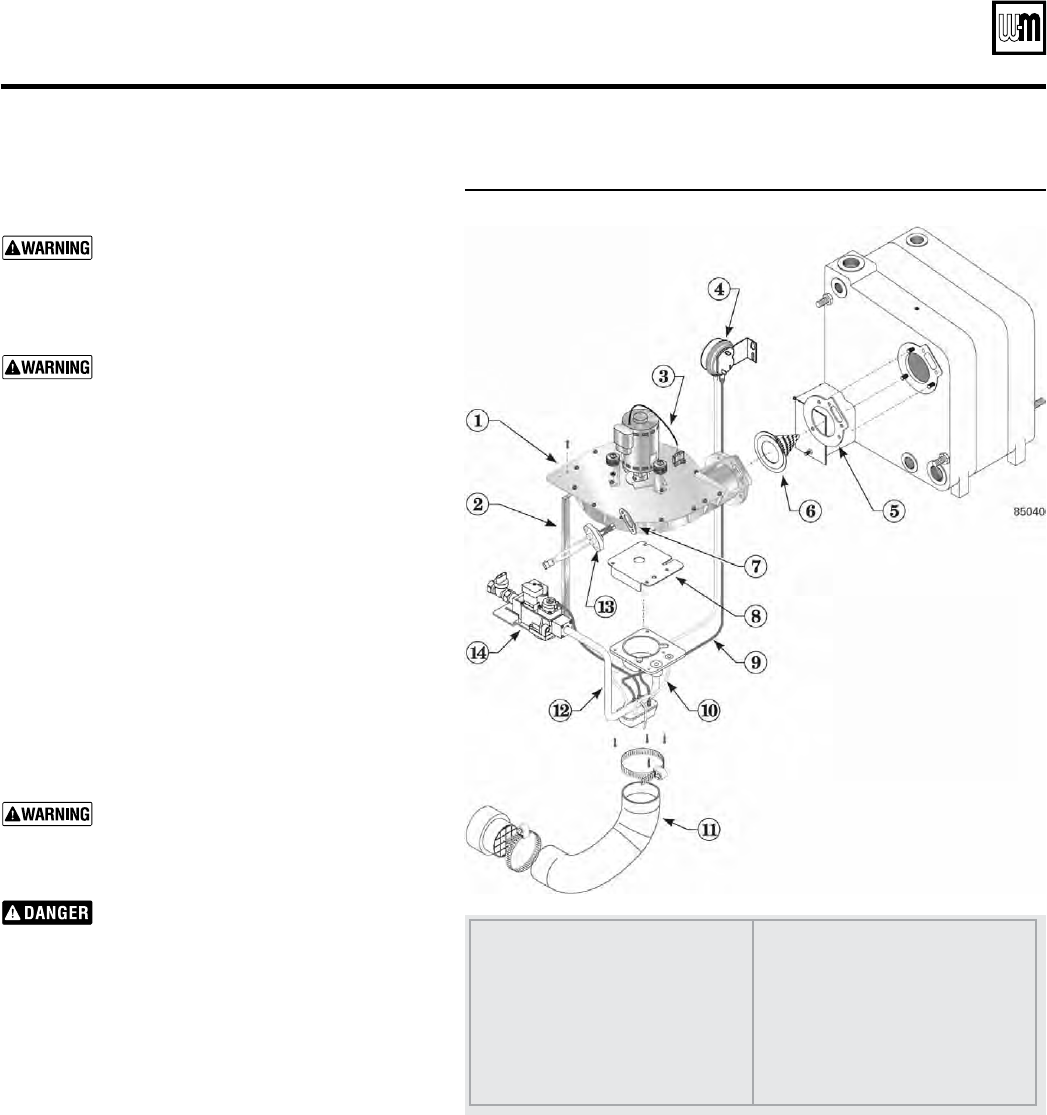
Figure 81 Blower housing removal procedure
1 Blower assembly
2 Blower support bracket
3 Blower motor wiring harness
4 Air pressure switch
5 Blower flange gasket (
replace this)
6 Burner cone and ring assembly
7 Igniter gasket (
replace this)
8 Gas/air orifice plate
9 Red pressure switch hose
10 White pressure switch hose
11 Inlet air hose and clamps
12 Gas tubing
13 Igniter
14 Gas valve and bracket
Cleaning boiler heating surfaces
The service procedures in this manual
must only be performed by a qualified
boiler service technician. Failure to com-
ply could result in severe personal injury,
death or substantial property damage.
The boiler contains ceramic fiber and
fiberglass materials. Use care when han-
dling these materials per instructions
on page 107 of this manual. Failure to
comply could result in severe personal
injury.
1. If inspection of the boiler flueways indicates the presence
of soot, cl
ean the boiler heating surfaces using the
following procedure. The process requires remov-
ing the blower housing to allow spraying water
through the boiler combustion chamber.
2. Before proceeding, obtain a GV90+ gasket replace-
ment kit, consisting of igniter, recuperator, flueway
inspection port and blower flange gaskets.
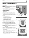
To remove the blower assembly
1. Turn off boiler by turning down the thermostat.
Then turn off power at the boiler service switch.
Close manual gas valve on incoming gas line to
boiler.
Turn off power and gas to the boiler.
Failure to do so can cause severe personal
injury, death or substantial property
damage.
Wait several minutes after boiler has
stopped to allow the igniter to cool to
avoid severe personal injury or death.
2. See Figure 81.
3. Disconnect:
a. Remove union outside of boiler
b. Gas tubing from gas valve outlet by removing
the 4 screws securing the outlet fitting to the
valve. (Save the o-ring in the fitting.)
c. Remove gas valve and bracket
d. Hose from gas valve to gas/air manifold
e. Pressure switch hoses
f. Air inlet hose
g. Blower motor wiring harness from IBC
h. Igniter harness connected to igniter plug
i. Blower support bracket (remove screw secur-
ing blower housing to bracket — on left side of
blower housing)
j. Ground wire.
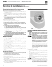
4. Remove the two igniter screws and washers. Care-
fully remove the igniter. Use care when handling —
igniter is very brittle. DO NOT touch igniter surface
with hands or expose to any greasy substances.
5. Remove nuts from studs securing blower housing
to front section.
6. Grasp blower housing and pull free from studs. Turn clockwise slightly,
until blower assembly can be removed safely from inside of boiler jacket.
7. Remove burner cone and gasket for inspection.
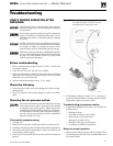
To clean heating surfaces
1. Remove the flueway inspection port cover (page 3, item g), if not al-
ready off of the boiler.
2. Place a catch pan under the inspection port to catch the cleaning
water.
3. Spray water into the boiler combustion chamber opening.
4. Catch the runoff water in the pan below the inspection port.
5. Continue process until flueways are clean.