


Part number 550-142-054/0411
21
GV90+ gas-fired water boiler — Boiler Manual
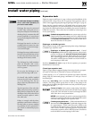
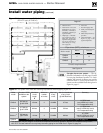
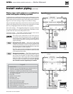
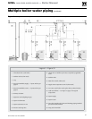
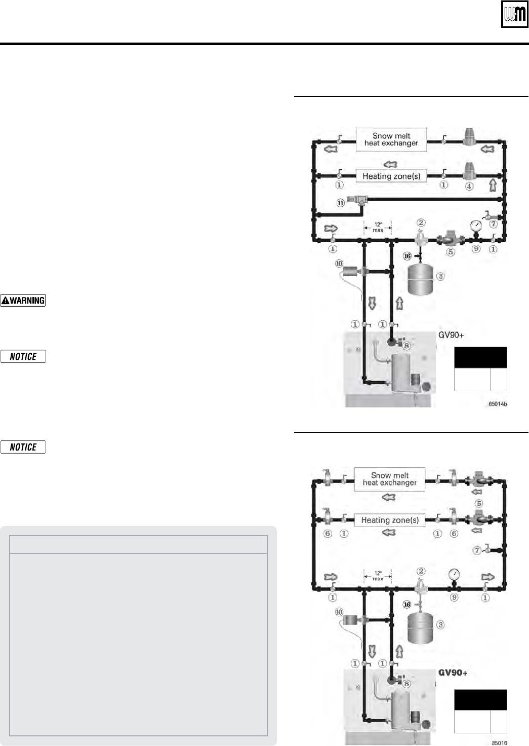
Figure 25 Auto return temp regulation — circulator
zoning
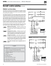
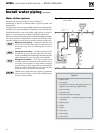
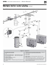
Piping snow melt systems or combination
snow melt/space heating systems
Combination snow melt/space heating systems can have return water
temperature below 60°F, and the return temperature will fluctuate. So
these systems require automatic return water temperature as shown in
Figure 25 (zone-valve zoning) or Figure 26 (circulator zoning).
Select an automatic temperature control valve or motor-operated valve
which can be adjusted to provide a return water temperature of at least
60°F. Any setting higher than 60°F will also be acceptable.
Zone-valve zoning — The suggested piping uses a separate circulator
for system circulation to assure good temperature distribution in the
system when the return water temperature is low.
Circulator zoning — The GV90+ internal circulators must not be
removed. Provide a separate circulator for each zone.
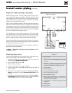
The return water temperature to the boiler must be
at least 60°F. Provide and apply means to regulate the
return temperature. Failure to do so can result in boiler
control operation problems, causing possible significant
property damage.
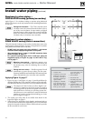
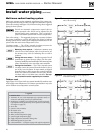
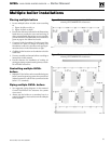
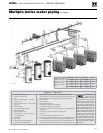
Zoning with zone valves
— Each zone in the piping
diagrams in this sect
ion
is shown with an isolation valv
e
on each side. Substitute a memory-stop valve for one of
the
se
in eac
h
zon
e
in ord
er
to use the mem
ory-stop
valv
e
for balancing flow as well as isolation.
Provide
a sep
arate
24-
volt
tra
nsformer
to pow
er
the zon
e
val
ves.
Siz
e
the tra
nsformer
to han
dle
the tot
al
rat
ed
load
of all co
nnected
zo
ne
val
ves.
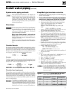
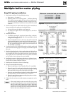
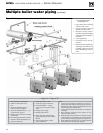
Zoning with circulators — The GV90+ internal system
circulator cannot be removed from the boiler for use as
one of the zone circulators. It must remain as shipped
from the factory to allow proper flow control inside the
boiler. You will need a circulator for each zone. Provide
circulator relays or circulator zone controller.
The sys-
tem circulator must be supplied by the installer.
MINIMUM
Boiler loop pipe size
GV90+3/4
GV90+5/6
1”
1¼”
MINIMUM
Boiler loop pipe size
GV90+3/4
GV90+5/6
1”
1¼”
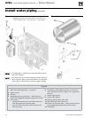
Legend
1 Isolation valves
2 Automatic air vent (with diaphragm-type expansion tank), or
connect to tank fitting (closed-type expansion tank).
3 Diaphragm- or bladder-type expansion tank, if used (For closed-
type expansion tank, pipe from top of air separator to tank fitting
as in Figure 15, page 14.)
4 Zone valve
5 System or zone circulator
6 Flow/check valve
7 Hose bibb purge valve
8 Boiler pressure/temperature gauge
9 System supply temperature gauge
10 Return temperature automatic mixing valve
11 Differential pressure by-pass valve
16 Cold water fill line — see Figure 15, page 14 for typical components
Figure 26 Auto return temp regulation — zone valve
zoning
Install water piping (continued)