


Part number 550-142-054/0411
43
GV90+ gas-fired water boiler — Boiler Manual
DIRECT VENT — Vertical with separate pipes
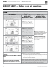
Allowable vent/air pipe materials &
lengths
Use only the vent materials and kits listed
in Figure 40, page 33. Provide pipe adapt-
ers if specified.
1. Locate the terminations such that the total air pip-
ing and vent piping from the boiler to the termina-
tion will not exceed the maximum length given in
Figure 39, page 32.
Determine termination location
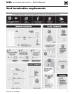
1. The air and vent terminations must be installed as
shown in Figure 53, page 43.
2. The terminations must comply with clearances and
limitations shown in Figure 41, page 35.
3. Locate the terminations so they are not likely to be
damaged by foreign objects, such as stones or balls,
or subject to buildup of leaves or sediment.
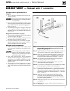
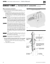
Multiple vent/air terminations (Figure 54)
1. When terminating multiple GV90+ boilers, ter-
minate each vent/air connection as described in
this section.
Terminate all vent pipes at the same
height and all air pipes at the same height
to avoid possibility of severe personal
injury, death or substantial property
damage.
2. Place roof penetrations to obtain minimum clear-
ance of 12 inches between edge of air intake elbow
and adjacent vent pipe of another boiler for U. S.
installations (see Figure 54, page 44). For Canadian
installations, provide clearances required by CSA
B149.1 or B149.2 Installation Code.
3. The air inlet of a GV90+ boiler is part of a direct
vent connection. It is not classified as a forced air
intake with regard to spacing from adjacent boiler
vents.
Prepare roof penetrations
1. Air pipe penetration:
a. Cut a hole for the air pipe. Size the air pipe
hole as close as desired to the air pipe outside
diameter.
2. Vent pipe penetration:
a. Cut a hole for the vent pipe. For either combus-
tible or noncombustible construction, size the
vent pipe hole at least 0.4” larger than the vent
pipe diameter (4” hole for 3” PVC).
b. Insert a galvanized metal thimble in the vent
pipe hole.
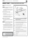
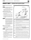
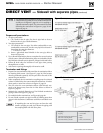
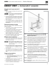
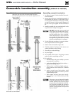
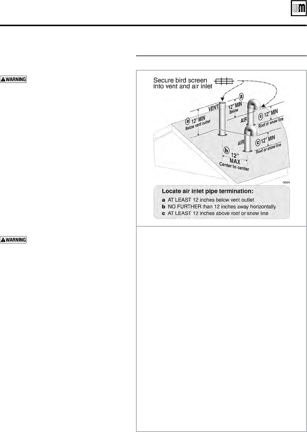
Figure 53 Separate pipes vertical termination
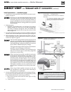
Step 1 Read and follow all instructions in this manual. DO NOT proceed
with vent/air installation until you have read page 29
through page 35.
Step 2 Install the boiler in a location that allows proper routing of all vent
and air piping to the selected sidewall location.
Step 3 Make sure the selected vertical termination location complies with
Figure 41, page 35. (Multiple boiler terminations must also comply
with Figure 54, page 44.)
Step 4 Use only the vent materials listed in Figure 40, page 33. Provide pipe
adapters where required. Vent piping and air piping lengths must not
exceed the values shown in Figure 39, page 32.
Step 5 Prepare the vertical penetrations and secure penetration components
as instructed in this section. See “Prepare roof penetrations” on page 43
and “Termination and fittings” on page 44.
Step 6 The air piping must terminate in a 180-degree return bend or down-
turned elbow as shown above. The vent piping must terminate in a
coupling pointed upward as shown above.
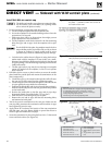
Step 7 Install vent and air piping between the boiler and the vertical termina-
tions. Slope horizontal piping downward toward the boiler at least 1/4
inch per foot. Install pipe supports every 5 feet on both the horizontal
and vertical runs. Install a hanger support within 6 inches of any upturn
in the piping. See page 48 for general guidelines.
Step 8 Insert the vent and air piping through the vertical penetrations and
secure the termination fittings.
Step 9 Maintain clearances shown above. Vent and air terminations must be
fitted with a bird screen as shown.