


Part number 550-142-054/0411
53
GV90+ gas-fired water boiler — Boiler Manual
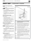
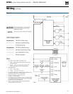
DIRECT EXHAUST — Vertical
Allowable vent/air pipe materials &
lengths
Use only the vent materials and kits listed
in Figure 40, page 33. Provide pipe adapt-
ers if specified.
1. Locate the termination such that the total air piping
and vent piping from the boiler to the termina-
tion will not exceed the maximum length given in
Figure 39, page 32.
Determine termination location
1. The vent terminations must be installed as shown
in Figure 63, page 53.
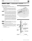
2. The terminations must comply with clearances and
limitations shown in Figure 41, page 35.
3. Locate the termination so it is not likely to be dam-
aged by foreign objects, such as stones or balls, or
subject to buildup of leaves or sediment.
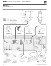
Multiple vent/air terminations
1. Terminate each vent of multiple direct exhaust
GV90+ boilers as described in this manual for
individual vents.
2. Space terminations as required for best installation
practices and required maintenance.
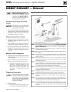
Prepare roof penetration
1. Vent pipe penetration:
a. Cut a hole for the vent pipe. For either com-
bustible or noncombustible construction, size
the vent pipe hole at least 0.5” larger than the
vent pipe diameter.
b. Hole diameter in the metal plates must be at
least 4” for PVC pipe. For AL29-4C vent pipe
and coupling (or elbow) — size hole 0.5” larger
than vent pipe outside diameter.
c. Insert a galvanized metal thimble in the vent
pipe hole.
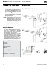
2. Follow all local codes for isolation of vent pipe when
passing through floors, ceilings and roofs.
3. Provide flashing and sealing boots sized for the vent
pipe and air pipe.
Where the vent penetrates the roof, the an-
nular space around the penetration must
be permanently sealed using approved
materials to prevent entry of combustion
products into the building.
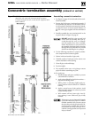
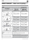
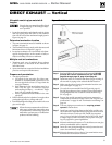
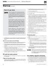
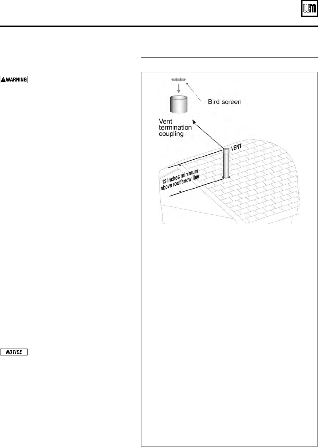
Figure 63 INSTALLATION SEQUENCE — Direct exhaust vertical
Step 1 Read and follow all instructions in this manual. DO NOT
proceed with vent/air installation until you have read
page 29 through page 35, page 49 and page 50.
Step 2
Install the boiler in a location that allows proper routing of
all vent and air piping to the selected sidewall location.
Step 3 Make sure the selected vertical termination location com-
plies with Figure 41, page 35.
Step 4 Use only the vent materials listed in Figure 40, page 33.
Provide pipe adapters where required. Vent piping and air
piping lengths must not exceed the values shown in Fig-
ure 39, page 32.
Step 5 Prepare the vertical penetration and secure penetration
components as instructed in this section. See “Prepare roof
penetrations” on page 43 and “Termination and fittings” on
page 44.
Step 6 The vent piping must terminate in a coupling pointed
upward
as shown above.
Step 7 Install vent and air piping between the boiler and the verti-
cal termination. Slope horizontal piping downward toward
the boiler at least 1/4 inch per foot. Install pipe supports
every 5 feet on both the horizontal and vertical runs. Install
a hanger support within 6 inches of any upturn in the pip-
ing. See page 48 for general guidelines.
Step 8 Maintain minimum clearance of C\zn inch between vent pipe
and any combustible wall or material.
Step 9 Insert the vent piping through the vertical penetration and
secure the termination coupling.
Step 10 Maintain clearances shown above. Vent terminations must
be fitted with a bird screen as shown.