


Part number 550-142-054/0411
GV90+ gas-fired water boiler — Boiler Manual
44
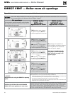
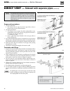
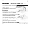
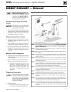
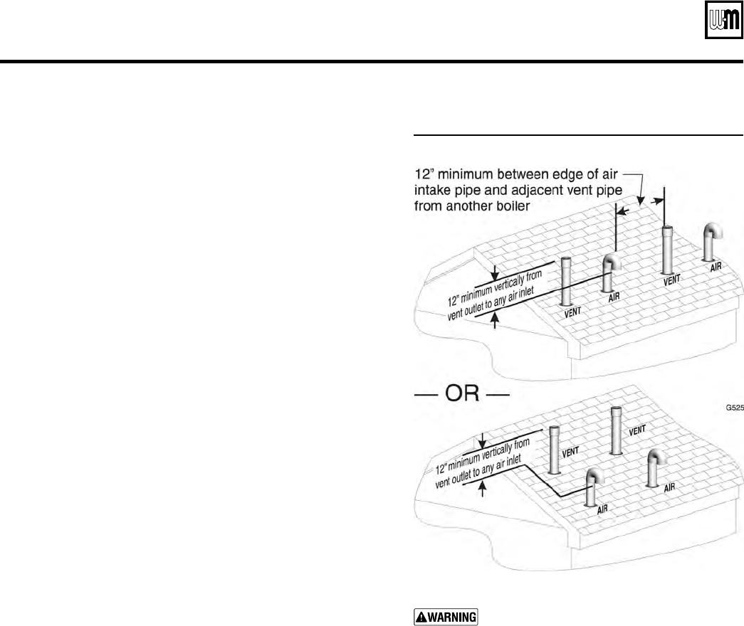
Figure 54 Terminations for multiple boilers
Also maintain maximum center-to-center
distances between the vent and air pipes for
each boiler as shown in Figure 53, page 43.
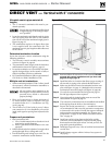
DIRECT VENT — Vertical with separate pipes (continued)
3. Space the air and vent holes to provide the minimum spacings
shown in Figure 53, page 43.
4. Follow all local codes for isolation of vent pipe when passing
through floors, ceilings and roofs.
5. Provide flashing and sealing boots sized for the vent pipe and air
pipe.
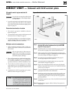
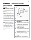
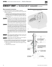
Termination and fittings
1. Prepare the vent termination elbow and the air termination elbow
(Figure 53, page 43) by inserting bird screens. Bird screens must be
purchased separately. See the parts list at the end of this manual
for part numbers.
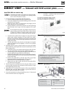
2. The air piping must terminate in a down-turned 180-degree re-
turn bend as shown in Figure 53, page 43. Locate the air inlet pipe
no further than 12 inches from the center of the vent pipe. This
placement avoids recirculation of flue products into the combus-
tion air stream.
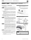
3. The vent piping must terminate in an up-turned coupling as shown
in Figure 53, page 43. The top of the coupling must be at least 1
foot above the air intake. The air inlet pipe and vent pipe can be
located in any desired position on the roof, but must always be no
further than 12 inches apart and with the vent termination at least
1 foot above the air intake.
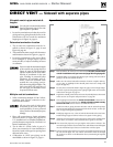
4. Maintain the required dimensions of the finished termination
piping as shown in Figure 53, page 43.
5. Do not extend exposed vent pipe outside of building more than
shown in this document. Condensate could freeze and block vent
pipe.