


Part number 550-142-054/0411
17
GV90+ gas-fired water boiler — Boiler Manual
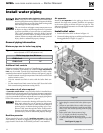
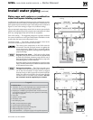
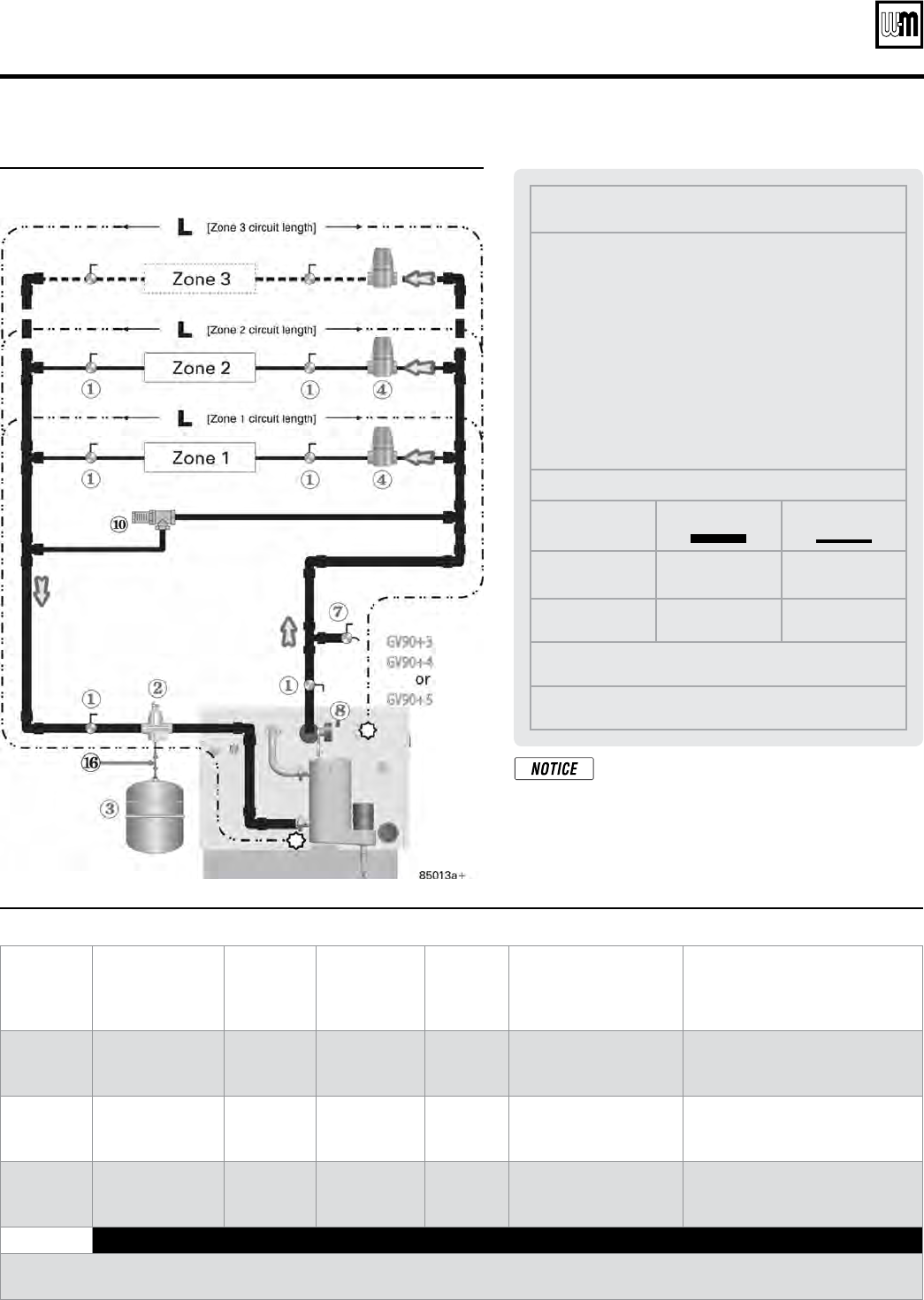
Legend
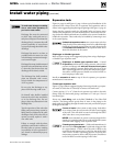
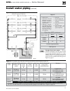
1 Isolation valves
2 Automatic air vent (with
diaphragm-type expan-
sion tank), or connect to
tank fitting (closed-type
expansion tank).
3 Diaphragm- or bladder-
type expansion tank, if
used. (For closed-type
expansion tank, pipe from
top of air separator to
tank fitting as in Fig-
ure 15, page 14.)
4 Zone valve
7 Hose bibb purge valve
8 Boiler pressure/tempera-
ture gauge
10 Differential pressure by-
pass valve
16 Cold water fill line — see
Figure 15, page 14 for
typical components
Pipe sizes (NPT), minimum
Boiler model
Mains
Circuits
GV90+3
GV90+4
1" ¾"
GV90+5 1¼" ¾"
Circuit requirements
See Figure 19
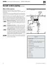
Install water piping (continued)
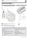
Figure 18 Zone valve zoning — GV90+3, GV90+4 or GV90+5
(DO NOT apply to GV90+6)
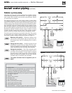
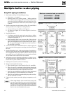
Figure 19 The system must meet the following requirements when applying Figure 18
Boiler
model
Circulator HEAD
available to the
system
Maximum
circuit
length
L
Minimum
number
of circuits
Max load
of any
circuit
Max feet baseboard
of any circuit
(@ 600 Btuh/foot)
Summary
GV90+3
6.4 feet w.c.
@ 6.5 GPM
103 feet 2 40 MBH 67 feet
6.5 GPM total
(max 4GPM any cricuit)
20°F temperature drop
GV90+4
4.1 feet w.c.
@ 9.7 GPM
92 feet 3 33 MBH 55 feet
9.7 GPM total
(max 3.3 GPM any circuit)
20°F temperature drop
GV90+5
*
5.5 feet w.c.
@8.7 GPM
112 feet 3 53 MBH 88 feet
8.7 GPM
(max 3.5 GPM any circuit)
30°F temperature drop
GV90+6 DO NOT apply to GV90+6 — Use primary/secondary piping ONLY, as in Figure 20, page 18.
* This application may be marginal. It could cause temperature distribution problems, because the temperature drop is 30°F,
NOT 20°F. The best method is to use primary/secondary piping for the GV90+5 as in Figure 20, page 18.
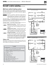
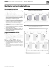
One-pipe diverter tees systems
— The ap-
plication
inf
ormation
on thi
s
page is bas
ed
on two
-pipe
bas
eboard
sys
tems.
To check
whether the internal circulator can provide
sufficient flow to a one-pipe diverter tee
system, use the available head value given in
Figure 19, page 17.