


Part number 550-142-054/0411
25
GV90+ gas-fired water boiler — Boiler Manual
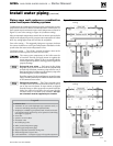
Multiple boiler water piping (continued)
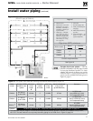
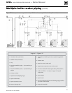
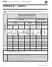
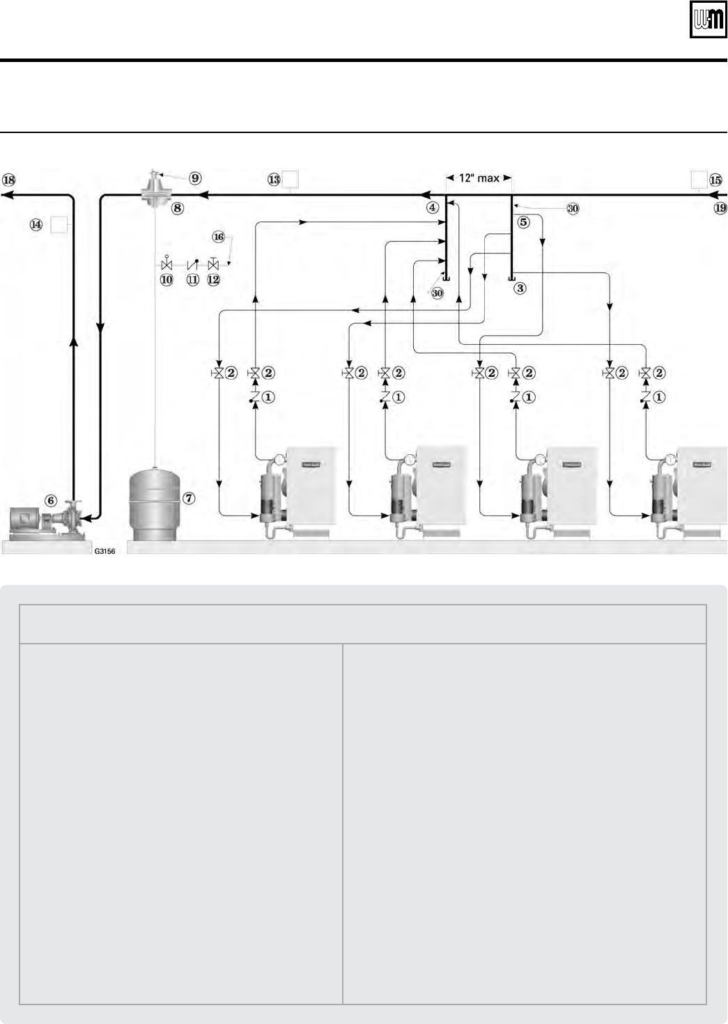
Legend — Figure 32
1 Flow/check valve (each boiler)
2 Isolation valves (when used)
3 Cap
4 Easy-Fit® Manifold (supply) — layout and size per
page 24
5 Easy-Fit® Manifold (return) — layout and size per
page 24
6 Primary circulator
7 Expansion tank (diaphragm type)
8 System air eliminator
9 System automatic air vent
10 Pressure reducing valve
11 Check valve or backflow preventer, as required by applicable
codes
12 Isolation valve
13 Water flow switch (when used)
14 Supply water temperature control (when used)
15 Low water cutoff (when used) (place above primary header)
16 Cold water fill line — see Figure 15, page 14 for typical
components
18 System supply
19 System return
20 (Not shown) Boiler relief valve and discharge piping, installed
per GV90+ Boiler Manual
30 Long end of manifold
Figure 32 Piping schematic — typical for multiple GV90+ boilers, using Weil-McLain Easy-Fit manifolds