


Part number 550-142-054/0411
GV90+ gas-fired water boiler — Boiler Manual
26
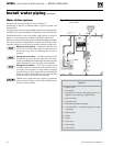
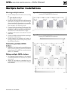
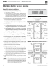
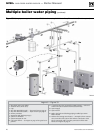
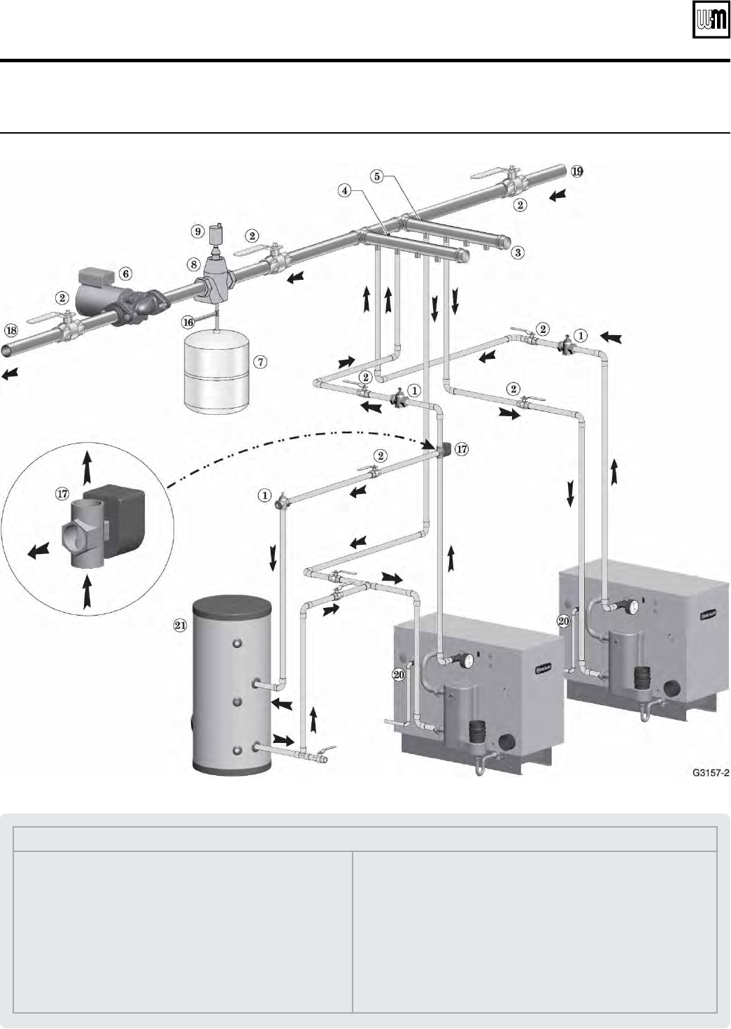
Multiple boiler water piping (continued)
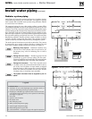
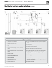
Legend — Figure 33
1 Flow/check valve (each boiler)
2 Isolation valves (when used)
3 Caps
4 Easy-Fit® Manifold (supply) — layout and size per page 24
5 Easy-Fit® Manifold (return) — layout and size per page 24
6 Primary circulator
7 Expansion tank (diaphragm type)
8 System air eliminator
9 System automatic air vent
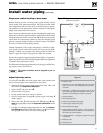
16 Cold water fill line — see Figure 32, page 25 for typical com-
ponents
17 3-way diverting valve (operated by DHW aquastat — valve end
switch connects across boiler thermostat terminals)
18 System supply
19 System return
20 Boiler relief valve and discharge piping, installed per GV90+
Boiler Manual
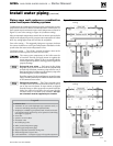
21 Indirect-fired storage water heaters — Example is shown connect-
ed to one boiler of the system. The indirect water heater could
also be connected with a secondary connection off the main
header, as in Figure 34, page 27.
Figure 33 Piping layout — typical for multiple GV90+ boilers, using Weil-McLain Easy-Fit manifolds (2-boiler system)