


Part number 550-142-054/0411
75
GV90+ gas-fired water boiler — Boiler Manual
Troubleshooting
VERIFY PROPER OPERATION AFTER
SERVICING.
Label all wires prior to disconnection when servicing
controls. Wiring errors can cause improper and danger-
ous operation.
Never jumper (bypass) any device except for momentary
testing as outlined in Troubleshooting charts. Severe
personal injury, death or substantial property damage
can result.
The IBC and boiler controls can malfunction if they get
wet. Never try to use a control that has been flooded or
wet. Replace it. Failure to comply can result in severe
personal injury, death or substantial property damage.
The boiler contains ceramic fiber and fiberglass materials.
Use care when handling these materials per instructions
on page 107 of this manual. Failure to comply could
result in severe personal injury.
Before troubleshooting
1. Have a voltmeter that can check 120 VAC, 24 VAC, 24 VDC and
a continuity checker.
2. Check for 120 VAC (min. 102-max.132) to boiler.
3. Make sure thermostat is calling for heat and contacts (including
appropriate zone controls) are closed. Check for 24 VAC between
thermostat wire nuts and ground.
4. Have an inclined manometer with 0 – 2” w.c. range.
Check the following
1. Wire connectors to IBC are securely plugged in at IBC and origi-
nating control.
2. Hoses are properly and securely plugged in and are not dam-
aged.
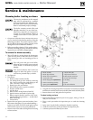
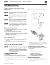
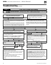
Checking the air pressure switch
Do not use manometer as shown in Figure 85 to test gas
valve outlet pressure. Where instructed in this manual
to check gas valve outlet pressure, follow instructions
carefully, particularly regarding connection of manom-
eter. Manometer fluid will cause permanent damage to
gas valve. Severe personal injury, death or substantial
property damage can result.
Check switch pressure setting
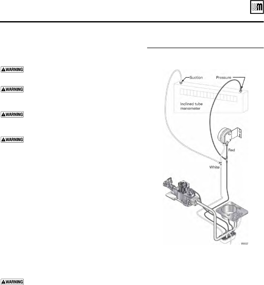
1. See Figure 85.
2. Remove both air pressure switch hoses from air pressure switch.
3. Install tees and tubing as shown in Figure 85 to inclined manometer.
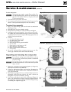
4. Turn off gas valve and set thermostat to call for heat. Blower will
run but burner will not ignite.
5. Check for 24 VAC between both air pressure switch terminals and
ground.
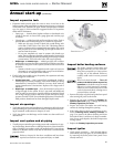
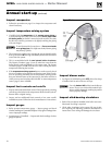
Figure 85 Connecting a manometer to check
air pressure switch. DO NOT use this
arrangement to check gas valve
6. If manometer reading is at least 1.0” w.c., but there is
not 24 VAC between both air pressure switch terminals
and ground, replace air pressure switch.
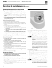
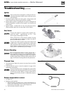
Troubleshooting air pressure reading
1. If manometer reading is lower than 1.4” w.c. check for
possible causes:
• Blockage in hoses.
• Loose blower wheel on motor shaft.
• Blower motor not at proper rpm.
• Blockage in air inlet or hose.
• Blockage in flue pipe or termination.
• Condensate trap filled w/condensate.
Return to normal operation
1. When pressure reading is proper and air pressure switch
is operating properly, remove tees and reinstall hoses to
air pressure switch.