


Part number 550-142-054/0411
73
GV90+ gas-fired water boiler — Boiler Manual
Service & maintenance (continued)
To clean the burner
The burner may contain ceramic fiber particles. Use
care when handling these materials per instructions on
page 107 of this manual. Failure to comply could result
in severe personal injury.
1. Clean the burner ports with a soft brush.
2. Use compressed air to blow out any particulate if necessary. Use
caution to avoid particulate being blown into the building.
To replace blower assembly
1. Place a new blower flange gasket over the studs at combustion
chamber opening.
2. Reinstall burner cone into chamber opening.
3. Position blower assembly over studs. Install nuts and tighten.
4. Install igniter and new igniter gasket. Fasten with screws and wash-
ers. Tighten only with hand-held screwdriver. DO NOT use electric
or pneumatic driver. Excessive torque will damage igniter. Do not
exceed 20 inch-pounds torque.
5. Connect:
a. Gas valve and piping (4 screws)
b. Gas tubing to gas valve outlet
c. Pressure switch hoses
d. Hose from gas valve to gas/air manifold
e. Air inlet hose
f. Blower motor wiring harness to IBC
g. Igniter harness to igniter plug
h. Blower support bracket (with screw)
i. Ground wire.
6. Be sure all wiring and hose connections are correct per Fig-
ure 81, page 72and are secure on the hose barb fittings.
Inspecting and cleaning the recuperator
Turn off power and gas to the boiler. Failure to do so
can cause severe personal injury, death or substantial
property damage.
Wait several minutes after boiler has stopped to allow
the boiler components to cool to avoid severe personal
injury or death.
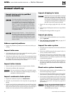
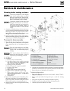
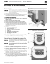
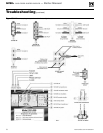
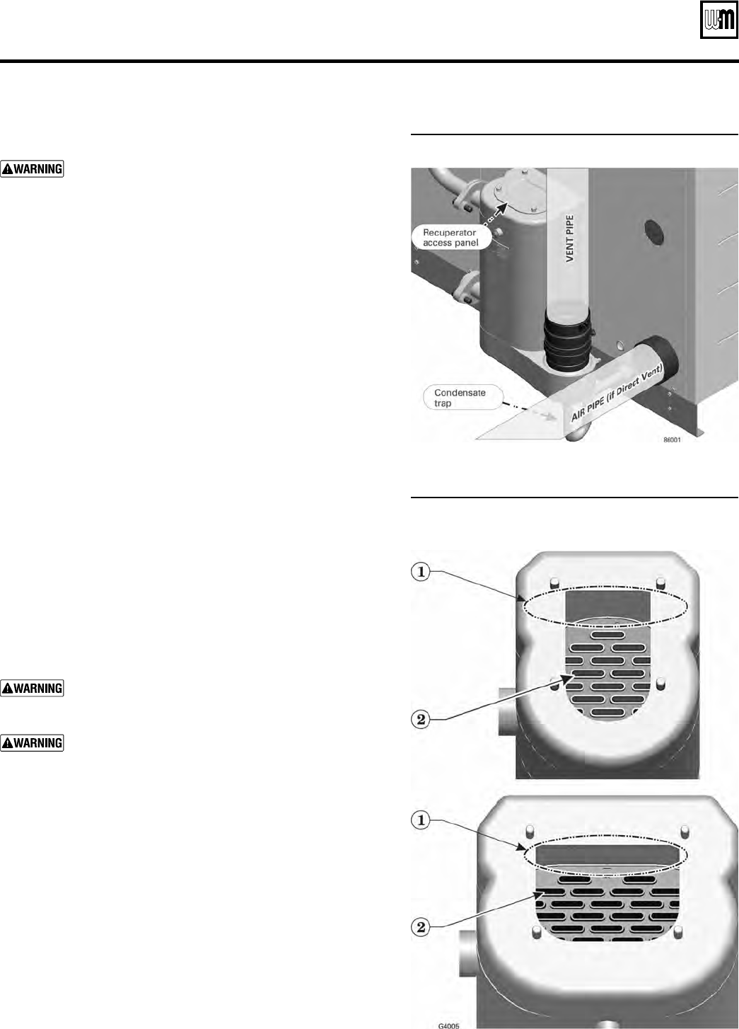
1. Remove the recuperator access panel and gasket (see Figure 82)
and inspect the interior with a flashlight.
2. If there are indications of debris or corrosion, disconnect the
condensate trap from the bottom of the recuperator and place a
catch pan underneath.
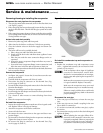
3. Flush the flueway (Figure 83, item 1) and tubes (Figure 83, item 2)
thoroughly with fresh water, allowing the water to drain out
through the recuperator condensate opening.
4. If all of the water doesn't drain from the flueway (Figure 83,
item 1), the drain holes (see Figure 84) may be plugged. Remove
the recuperator using the procedure under Removing/cleaning/
re-installing the recuperator, page 74.
Figure 82 Recuperator access and cleaning
Figure 83 Recuperator with access panel removed
(GV90+3/4 top, GV90+5/6 bottom)