


8
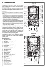
XPAK 85
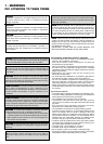
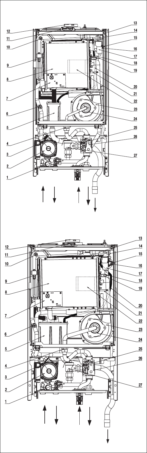
Fig. 1
GF
R
P
C
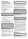
5 - INTRODUCTION
The XPak boiler is a wall hung, fan assisted, direct vent, heating
boiler only. These boilers – by design – incorporate electronic
ignition, circulating pump, pressure relief valve, pressure gauge,
and automatic bypass.
As supplied, the boiler will automatically modulate to provide
central heating outputs between 25,600 - 87,000 Btu/hr (7.5-25.5
kW) - XPak 85 and 27,300 - 119,500 Btu/hr (8-35 kW) XPak 120.
IMPORTANT
It is the law that all gas appliances are installed by a competent
person.
It is in your own interest and that of safety to ensure that the law is
complied with.
• The installation must conform to the requirements of the authority
having jurisdiction or, in the absence of such requirements, to
the National Fuel Gas Code, ANSI Z223.1/NFPA 54 Where
required by the authority having jurisdiction, the installation must
conform to the Standard for Controls and Safety Devices for
Automatically Fired Boilers, ANSI/ASME CSD-1.
• The installation should conform with CGA B149 INSTALLATION
CODE and/or local installation Code, plumbing or waste water
codes and other codes as applicable.
• Clearances from combustible material must be strictly adhered to.
• Manufacturers instructions must NOT be interpreted in anyway
as overriding statutory obligations.
The XPak family comprises a range of high-efficiency hot water
boilers with outputs ranging from 87,000 Btu/hr (25.5 kW) to
119,500 Btu/hr (35 kW). Each appliance is provided with a fan
powered flue outlet with an annular co-axial combustion air intake
that can be rotated – horizontally – through 360 degrees for
various horizontal or vertical applications. The XPak can also be
used with two pipe flue vent system. These appliances are
designed for use with a sealed system only; consequently they
are not intended for use on open vented systems.
This booklet is an integral part of the appliance. It is therefore
necessary to ensure that the booklet is handed to the person
responsible for the property in which the appliance is located/
installed. A replacement copy can be obtained from Raypak
customer services.
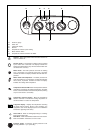
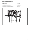
General layout (Fig. 1)
1 Water pressure switch
2 Pump
3 Bottom auto air vent (AAV)
4 Gas injector
5 Condense trap
6 Return sensor
7 H stamp main heat exchanger
8 Main heat exchanger
9 Flue thermostat
10 Flue sensor
11 Flue gas analysis test point
12 Flue outlet & air intake
13 Blocked flue switch
14 Top automatic air vent
15 Flow sensor
16 High limit thermostat
17 Ignition transformer
18 Sensing Electrode
19 Spark Electrode
20 Top automatic air vent drain pipe
21 Condensate level sensor
22 Cylindric Burner
23 Fan assembly
24 Mixer
25 Gas modulator coil
26 Gas valve
27 Pressure relief valve
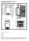
R Boiler IN connection
F Boiler OUT connection
G Gas connection
P Pressure relief valve drain
C Condensate drain pipe
XPAK 120
G
F
R
P
C