


41
7. CHECK THERMOSTAT CIRCUIT(S)
1. Disconnect the two external wires connected to the boiler
thermostat terminals (low voltage terminal strip M4a).
2. Connect a voltmeter across these two incoming wires. Close
each thermostat, zone valve and relay in the external circuit one
at a time and check the voltmeter reading across the incoming
wires.
3. There should NEVER be a voltage reading.
4. If a voltage does occur under any condition, check and correct
the external wiring.
5. Once the external thermostat circuit wiring is checked and
corrected if necessary, reconnect the external thermostat circuit
wires to boiler low voltage terminal strip. Allow the boiler to
cycle.
8. TESTING FOR GAS LEAKS
Prior to start-up of the boiler you must check the external tightness
of the gas supply valve and confirm this in the start-up report.
Inspect the entire installation including the gas meter.
WARNING:
Before starting the XPak, and during initial
operation, smell near the floor and around the heater for gas
odorant or any unusual odor. Remove heater front door and
smell interior of heater enclosure. Do not proceed with startup
if there is any indication of a gas leak. Repair any leak at once.
WARNING: LPG boiler only — Your propane supplier mixes
an odorant with the LPG to make its presence detectable. In
some instances, the odorant can fade, and the gas may no
longer have an odor. Before startup (and periodically
thereafter), have the LPG supplier verify the correct odorant
level in the gas.
WARNING:
- Cover endangered positions before leak testing.
- Do not spray the leak testing agent onto cables, plugs or
electrical connection lines.
- Do not allow it to drip onto them either.
DANGER: Leaks may be caused to pipes and screw
connections during commissioning and maintenance
activities.
- Carry out a proper leak test.
- Only use approved leak detection agents for leak detection.
- Disconnect the heating system from the power supply.
- Check the exterior tightness of new pipe sections up to
and including the direct sealing point on the gas burner
fitting.
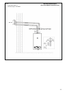
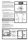
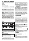
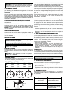
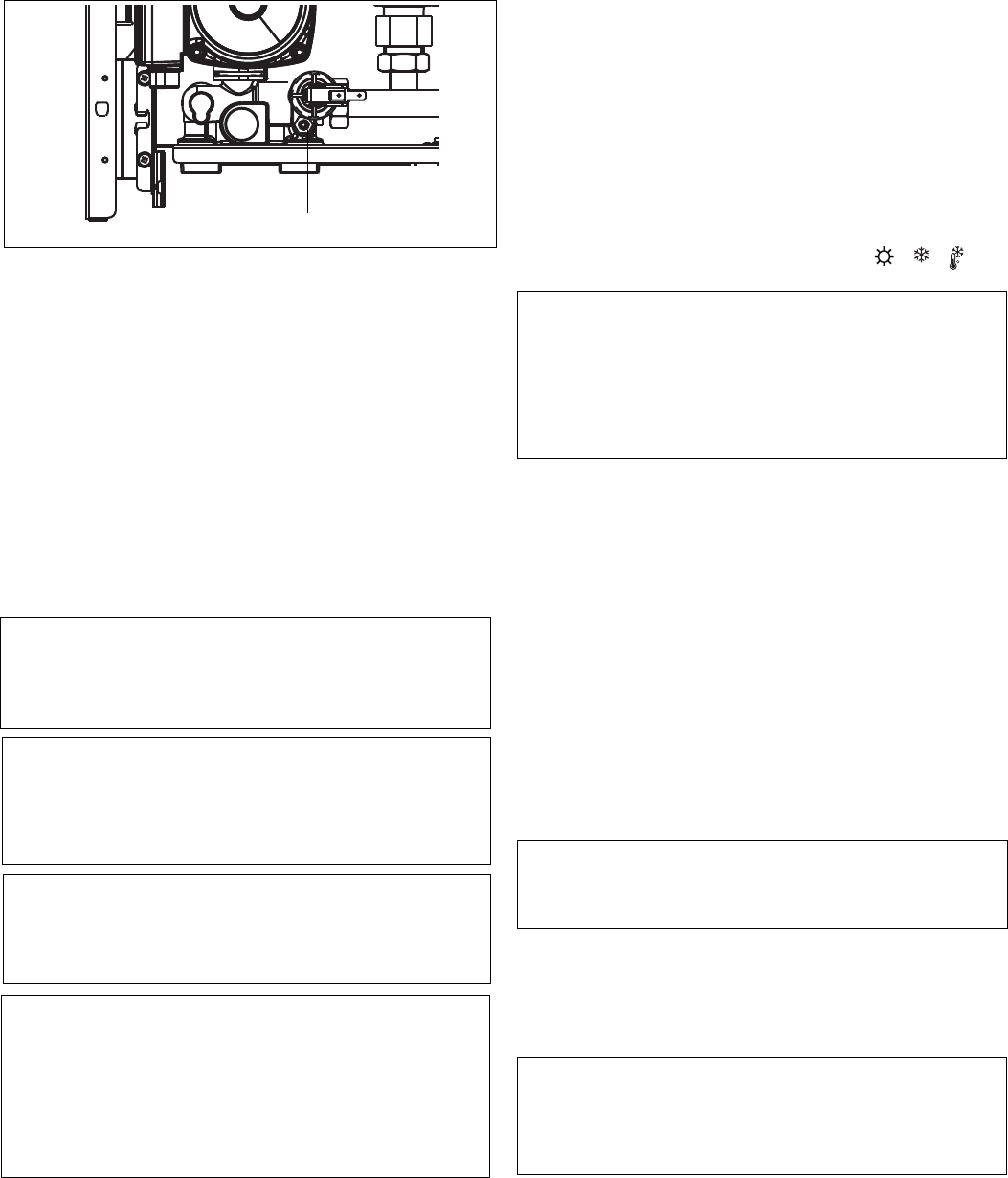
9. INITIAL FLUSHING OF THE SYSTEM
The whole of the heating system must be flushed both cold and
hot as detailed in Fig. 42a. Open all radiator or heating valves
and the boiler flow & return service valve. Drain the boiler and
system from the lowest points. Open the drain valve full bore to
remove any installation debris from the boiler prior to lighting.
Refill the boiler and heating system.
10. PRE-OPERATION CHECKS
Before attempting the initial lighting of the appliance, the following
checks must be carried out:
- Ensure all gas service valves from the meter to the appliance
are open and the supply pipe has been properly purged;
- Ensure the proper electrical checks have been carried out,
particularly continuity, polarity, and resistance to ground;
Fig. 42a
A
- Ensure the 4 AMP fuses are installed;
- Ensure the system has been filled, vented, and the pressure
set to 15 p.s.i. (1 bar);
- Ensure the flue system has been installed properly and in
accordance with the instructions;
- Ensure all appliance service valves are open.
11. INITIAL LIGHTING AND IGNITION SAFETY SHUTOFF
DEVICE TEST
Ensure the electrical supply to the appliance is switched on. Ensure
any external controls are switched to an ‘ON’ position and are
calling for heat.
Move the selector switch to the ON position (
- -
F
), the
appliance will now operate.
NOTICE:
After installation, the boiler must be turned ON and the
thermostat set for CFH and operated with the manual gas
shut-off valve below the unit closed. Allow the boiler to go
through its 5 ignition tries and then lock out. The display should
indicates the alarm code 10. After the test, reset the control,
open the gas valve, set the thermostat to the proper setting
and ensure that the boiler operates properly.
12.CHECKING GAS PRESSURE AND COMBUSTION
ANALYSIS
The boiler is factory set and requires no additional adjustment
once installed.
If the installation does not include a gas meter (for example LPG)
and there are no means by which to calculate the gas rate, then a
combustion analysis test must be carried out in accordance with
local regulations to ensure the appliance is left working safely
and correctly.
Additionally, if the gas valve has been adjusted, replaced, or the
appliance has been converted for use with another gas type,
then it becomes necessary to carry out a combustion analysis/
check to ensure that correct combustion is occurring.
If there are no means to gas rate the appliance and/or carry out a
combustion analysis check, then it will not be possible to comple-
te the commissioning procedure.
Details on how to carry out the combustion analysis can be found
in Section 11.
NOTICE: It’s imperative that a sufficient dynamic – gas –
pressure is maintained at all times. Should the dynamic gas
pressure fall below an acceptable level, the appliance may
malfunction or sustain damage.
13. FINAL FLUSHING OF THE HEATING SYSTEM
The system shall be flushed. Cleaners or chemicals used, must
be suitable for Aluminum heat exchangers and shall be from a
reputable manufacturer and shall be administered in strict
accordance with the manufacturers’ instructions.
NOTICE: Chemicals used to clean the system and/or inhibit
corrosion must be pH neutral, i.e. they should ensure that the
level of the pH in the system water remains neutral.
Premature failure of certain components can occur if the level
of pH in the system water is out of normal levels.
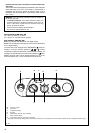
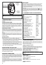
14. SETTING THE BOILER OPERATING TEMPERATURE
The flow outlet temperature can be adjusted between 104-176°F
(40-80°C) depending on the boiler configuration via the Heating
thermostat knob (Fig. 1A).
If the 3-way valve is connected, the flow outlet temperature to the
tank can be adjusted between 95-140°F (35-60°C) via the DHW
temperature selector (Fig. 1A).
15. REGULATING THE CENTRAL HEATING SYSTEM
Fully open all radiator and circuit valves and run the appliance for
both heating and hot water until heated water is circulating. If
conditions are warm remove any thermostatic heads. Adjust
radiator return valves and any branch circuit return valves until
the individual return temperatures are correct and are
approximately equal.