


54
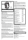
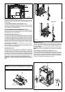
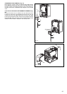
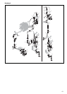
MAIN HEAT EXCHANGER (Fig. 76-77)
Unclip and remove the three air chamber covers (front, left hand,
right hand sides). Disconnect all the wiring connections.
Fig. 76: slacken the gas pipe (A) at the air box connection and
swing/rotate of the fan assembly. Disconnect the flow (B), return
(C) and condensation connections on the heat exchanger. Locate
and remove the 4-screws that secure the heat exchanger to the
combustion chamber (D). Move the heat exchanger to the right and
disconnect it from the flue collector (E). The heat exchanger can
now be lifted up and removed from the boiler.
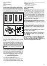
Fig. 77: to remove the fan burner assembly (A) locate and remove
the 3 external nuts (B). Replace in the reverse order. Ensure all
seals are in good condition, taking care to ensure they are
replaced correctly.
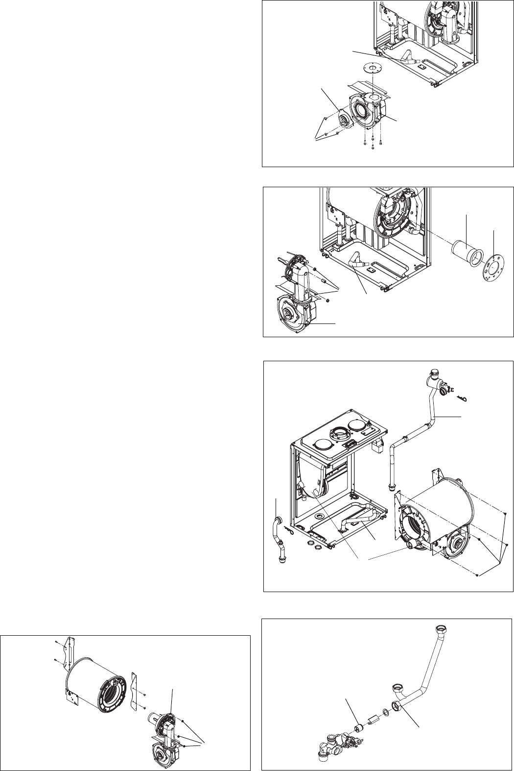
AUTOMATIC BYPASS (Fig. 78)
Disconnect and remove the flow pipe (1), at the connection to the
pressure relief valve, at heating manifold and at the connection
to the air chamber. Using a hooked piece of wire, carefully
withdraw the bypass cartridge (2).
Ensure all seals are in good condition, taking care to ensure they
are replaced correctly. Replace in the reverse order ensuring the
cartridge is facing the correct way.
Fig. 77
Fig. 78‘
A
B
D
E
F
C
Fig. 75
A
B
C
D
E
Fig. 76
B
A
1
2
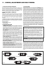
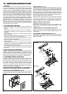
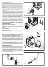
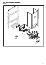
FLUE FAN & MIXER (Fig. 74)
Unclip and remove the air chamber front and the right hand side
covers. Slacken the gas pipe (A) at the air box connection and
swing/rotate away from the fan assembly. To remove the mixer
(B) locate and remove the three screws (C). To remove the fan
(D), disconnect the electrical connections attached to the fan,
locate and remove the four screws (E). Gently ease the fan from
its location.
Replace in the reverse order. Ensure all seals are in good
condition, taking care to ensure they are replaced correctly.
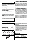
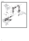
BURNER (Fig. 75)
Unclip and remove the air chamber front and the right hand side
covers. Slacken the gas pipe (A) at the air box connection and
swing/rotate of the fan assembly. Locate and remove the 3 internal
nuts (B) which secure the fan assembly in position (C) to the heat
exchanger (D). Disconnect the electrode leads and ancillary
wiring from their respective connectors. Remove the retaining
screws (A fig. 73) for sensing electrode and remove. Remove the
retaining nut (C fig. 73) for condensation sensor (D fig. 73) and
remove. Gently ease the fan assembly out of its location. Once
the assembly has been removed, the burner (E) can be withdrawn
from the heat engine. Ensure the seal (F) is in good condition,
taking care to ensure it is replaced correctly. Replace in the reverse
order.
BLOCKED FLUE PRESSURE SWITCH/IGNITION
TRANSFORMER (Fig. 73)
Disconnect the compensation pipe (G).
Disconnect the electric wiring from the pressure switch/ignition
transformer.
Remove the two screw (F) on the upper part of the combustion
chamber.
Remove the screw (I).
Remove the pressure switch. Replace in reverse order.
Remove the two screw (H), remove the ignition transformer.
Replace in reverse order.
Fig. 74
A
B
E
C
D