


17
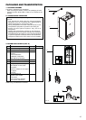
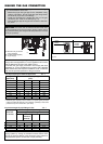
2. PLACING THE WALL-MOUNTED XPAK BOILER
XPak boilers are wall mounted. Use only the XPak boiler wall
mounting instructions included in the box.
WARNING:
The wall must be capable of carrying the weight
of the boiler and its related components. The weights of the
boiler are approximately:
XPak 85 = 82 lbs (37 kg).
XPak 120 = 93 lbs (42 kg).
Failure to comply with above could result in severe personal
injury, death or substantial property damage
3. XPAK WALL MOUNTING INSTRUCTIONS
WARNING:
This boiler is heavy and awkward to lift. It is
recommended and safer to install the boiler with two people.
Use caution as to not drop the boiler which could cause
personal injury. Verify that the boiler is securely mounted
before leaving the boiler unsupervised.
The wall must be vertically plumb and capable of carrying the
weight of the XPak and its related components.
The building frame (studs) must be 16" on center. If not, you must
use 1/2" minimum plywood 24" x 48", fastened with at least (14)
#12 x 3" (3/16" x 3") round head tapping screws to the frame of the
building to provide proper support for the boiler. Alternate methods
of mounting must not be used. (ex. toggle bolts, hollow wall
anchors) or any other fastener other than #12 x 3" (3/16" x 3") round
head tapping screws.
CAUTION:
If the XPak is not vertically plumb, improper and
unsatisfactory operation may occur. This will cause excessive
condensation build-up causing unnecessary maintenance
and nuisance fault codes.
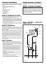
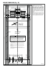
4. INSTALLATION STEPS
Prior to lifting the XPak Boiler onto the wall, use the enclosed
template to level and locate the wall bracket. Mount the wall
bracket using lag screws. Ensure the bracket is level when
mounted. Extreme care is needed to ensure the bolts are secured
in the studs. Hang the boiler on the bracket and secure the bottom
of the boiler with two (2) additional lag screws. This will provide
additional strength and support to the XPak boiler.
XPAK PIPING
1. RELIEF VALVE
The XPak has a pressure relief valve factory fitted.
Connect discharge piping to safe disposal location, following
guidelines in the WARNING below:
WARNING: To avoid water damage or scalding due to relief
valve operation:
- Discharge line must be connected to relief valve outlet and
run to a safe place of disposal. Terminate the discharge line
in a manner that will prevent possibility of severe burns or
property damage should the valve discharge.
- Discharge line must be as short as possible and be the same
size as the valve discharge connection throughout its entire
length.
- Discharge line must pitch downward from the valve and
terminate no more than 6” (150 mm) above the floor drain
where any discharge will be clearly visible.
The discharge line shall terminate plain, not threaded, with
a material serviceable for temperatures of 375 °F (190°C) or
greater.
- Do not pipe the discharge to any place where freezing could
occur.
- Do not plug or place any obstruction in the discharge line.
- Test the operation of the valve after filling and pressurizing
system by lifting the lever. Make sure the valve discharges
freely. If the valve fails to operate correctly, replace it with a
new relief valve.
- For boilers installed with only a pressure relief valve, the
separate storage vessel must have a temperature and
pressure relief valve installed. This relief valve shall comply
with the standard for Relief Valves for Hot Water Supply
Systems, ANSI Z21.22/CSA4.4.
- Failure to comply with the above guidelines could result in
failure of the relief valve to operate, resulting in possibility of
severe personal injury, death or substantial property damage.
2. GENERAL PIPING INFORMATION
CAUTION:
Use two wrenches when tightening water piping
at boiler, using one wrench to prevent the boiler return line or
supply line from turning. Failure to support the boiler piping
connections to prevent them from turning could cause damage
to boiler components.
NOTICE:
The XPak boiler control module uses temperature
sensors to provide both high limit protection and modulating
temperature control. The PCB also provides low water
protection using a water pressure switch (minimum 6.5 psi
(0.45 bar)) and blocked flue switch. Some codes/jurisdictions
may require additional external controls for high limit and/or
low water cutoff protection.
3. SEPARATE LOW WATER CUTOFF
A low water cutoff may be required by state local code or some
insurance companies. Check code requirements before
installation of the XPak boiler.
If required:
- Use a low water cutoff designed for hydronic installations
- Follow low water cutoff manufacturer’s instructions
NOTICE:
A hot water boiler installed above radiation level or as required
by the Authority having jurisdiction, must be provided with a
low water cut off device either as apart of the boiler or at the
time of the boiler installation.
4. BACKFLOW PREVENTER
Use a backflow preventer specifically designed for hydronic boiler
installations. This valve should be installed on the cold water fill
supply line per local codes.
5. FITTING THE HEATING CIRCUIT SUPPLY AND RETURN
PIPES
NOTICE:
- To protect the entire heating system Raypak recommends
installing a filter in the return circuit. When connecting the
boiler to an existing heating system this filter must definitely
be installed.
- Install shut-off valves immediately before and after the dirt
particle filter to enable the filter to be cleaned.
- Install a filling and drain cock in the heating system supply
pipe if required.
- Also install a safety valve in the system.
NOTICE: When using oxygen-permeable pipes, e. g. for floor
heating systems, you must separate the system using heat
exchangers.
- Thoroughly flush all pipes and radiators.
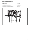
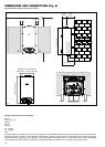
- Refer to the installation template for the pipe connection
dimensions.
- Connect the pipes so that they are free from strain.
6. EXPANSION TANK AND MAKE-UP WATER
1. Ensure expansion tank size will handle boiler and system
water volume and temperature. Allow 2 gallons for the boiler
and its piping.
CAUTION: Undersized expansion tanks cause system water
to be lost from relief valve and makeup water to be added
through fill valve. Eventual failure can result due to excessive
make-up water addition.
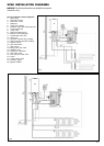
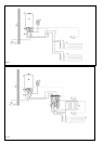
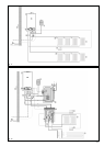
2. Expansion tank must be located near to the boiler as shown
in Piping “XPak installation diagrams”. No valve is to be placed
between the boiler and the expansion tank.
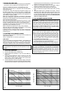
7. SIZING SPACE HEAT SYSTEM PIPING
- Size the piping and components in the space heating system
using recognized design methods.
NOTICE:
- The boiler, when used in connection with a refrigeration
system, must be installed so the chilled medium is piped
in parallel with the boiler and with appropriate valves to
prevent the chilled medium from entering the boiler.
- The boiler piping system of a hot water boiler connected to
heating coils located in air handling units where they may
be exposed to refrigerated air circulation must be equipped
with flow control valves or other automatic means to prevent
gravity circulation of the boiler water during the cooling cycle.