


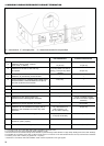

34
Fig. 34Fig. 33
B
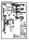
7 - ELECTRICAL CONNECTIONS
Devices such as outdoor sensor, 3-way valve, tank sensor, tank
thermostat, remote controls are all connected to the external
connection board.
The electrical connections to the boiler must be made in
accordance with all applicable local codes and the latest revision
of the National Electrical Code, ANSI/NFPA-70.
Installations should also conform with CSA C22.1 Canadian
Electrical Code Part 1 if installed in Canada.
1. EXTERNAL CONNECTION BOARD CONNECTIONS
A qualified electrician should connect the electrical supply to the
appliance. If controls – external to the appliance – are required,
a competent person must undertake the design of any external
electrical circuits. ANY EXTERNAL CONTROL OR WIRING MUST
BE SERVED FROM THE SAME ISOLATOR AS THAT OF THE
APPLIANCE. Wiring to the appliance must be rated for operation
in contact with surfaces up to 194°F (90°C).
WARNING:
ELECTRICAL SHOCK HAZARD — For your
safety, turn off electrical power supply at service entrance
panel before making any electrical connections to avoid
possible electric shock hazard. Failure to do so can cause
severe personal injury or death.
NOTICE:
Wiring must be N.E.C. Class 1. If original wiring as
supplied with heater must be replaced, use only TEW 221°F
(105 °C) wire or equivalent. Heater must be electrically
grounded as required by National Electrical Code ANSI/
NFPA 70 — latest edition.
CAUTION: Label all wires prior to disconnection when
servicing controls. Wiring errors can cause improper and
dangerous operation.
Verify proper operation after servicing.
2. ELECTRICAL SUPPLY
The boiler requires a 120V 60Hz power supply. Ensure the
electrical supply is properly polarized.
The boiler must be grounded.
There must only be one common isolator, providing complete
electrical isolation for the boiler and any external controls using
PVC insulated cable 18 AWG x3C 105 °C /221°F.
All wiring must be installed in accordance with requirements of
National Electrical Code and any additional national, state, or
local code requirements having jurisdiction. All wiring must be
N.E.C. Class 1. The boiler must be electrically grounded in
accordance with the National Electrical Code, ANSI/NFPA No.
70-latest edition.
In Canada, installation must conform to CSA C22.1 Canadian
Electrical Code Part 1 and any local codes.
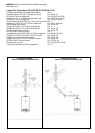
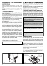
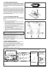
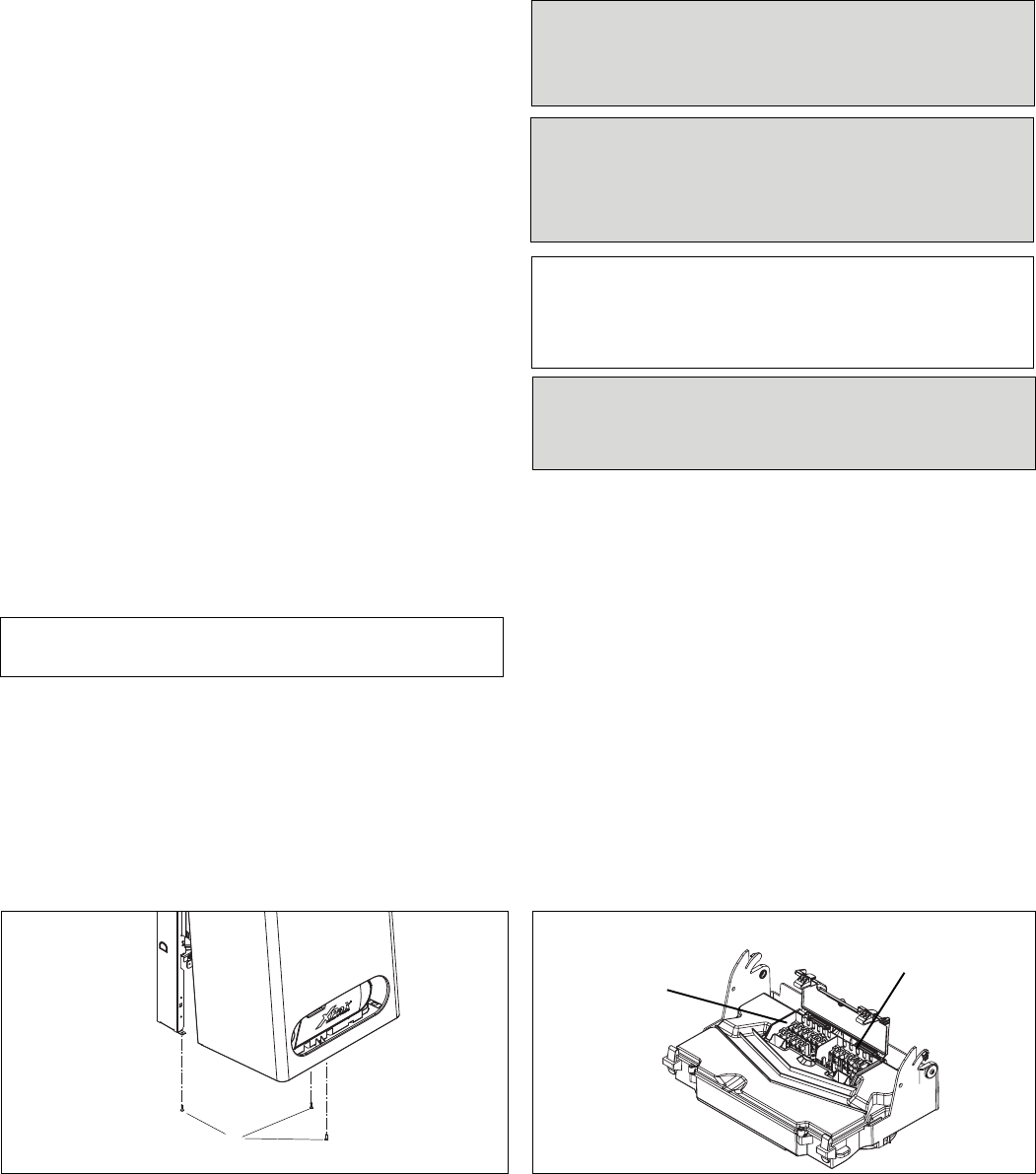
3. FIELD WIRING
The electrical junction box has a 24 volt terminal compartment and
120 volt terminal compartment. Each terminal connection is
clearly marked to ensure correct installation.
Optional devices
(24V) terminal block
Electrical
supply (120V)
terminal block
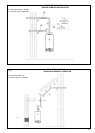
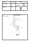
CONNECTING THE CONDENSATE
WATER DRAIN
The condensate formed both in the condensing boiler and in the
flue gas pipe must be discharged into the public sewage system
in accordance with all applicable local regulations.
The condensate produced by a gas-fired heating system has a
pH value between 3 and 4.
Some local codes may require the use of a separate neutralization
unit to treat the aggressive and corrosive condensate.
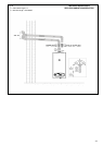
Raypak offers a Condensate Neutralizer Kit (Z-12 option) for use
when managing the condensate is desired or required. Order
part number 013141.
With a neutralization unit installed, all condensate from the boiler
and the flue gas pipe enters into the neutralization unit where it
is treated and released into the public sewage system with a
safe pH value of above 6.5.
The use of neutralization granulate (performing the neutralizing
process) is dependent on the operation of the heating system.
To determine the required refill amount, check granulate level
several times during the first year of operation. In some cases
one granulate fill may last an entire year.
The condensate discharge outlet to the drainage system
connection must be clearly visible. It must be installed with a
suitable gradient and provided with a stench trap.
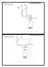
If the condensate outlet of the boiler is lower than the drain, a
condensate pump must be used (see electrical wiring to loch out
the boiler in the case of failure of the condensate pump - alarm 21).
Only corrosion-resistant materials may be used for condensate
drainage purposes (e.g. braided hose). Do not use galvanized
materials or materials containing copper for piping, couplings etc.
Please note that other requirements may apply depending on
local regulations and/or project-specific details.
It is advisable to contact your local waterworks office (authority
responsible for waste water regulations) well before
commencing with the installation of the neutralization unit in order
to establish details of local regulations that apply.
NOTICE: Pipe ventilation must take place between the
siphon trap and the neutralization unit (if applicable).
Install the condensate drain flexible pipe (Ø 0.825” - 21mm
female flexible rubber connection) with a suitable gradient (min.
2.5%).
Discharge condensate from the boiler into the drainage system,
either directly or (if required) via a neutralization unit (not
supplied).
1. CONDENSATE CONNECTION
The condensate drain of the boiler is equipped with a built-in
siphon trap in order to keep flue gases from being discharged
via the condensate drain.
AVERTISSEMENT:
RISQUE DE CHOC ÉLECTRIQUE —
Pour votre sécurité, coupez l'alimentation électrique au niveau
du tableau de distribution avant d'effectuer tout raccordement
électrique afin d'éviter un risque éventuel de choc électrique.
La non-observation du dernier point peut provoquer de
graves blessures ou la mort.