


12
BANNED MATERIAL STATEMENT:
No banned materials or substances have been used in the
manufacture or production of this appliance or its inherent
components
MANUAL HANDLING STATEMENT:
CAUTION:
This appliance may require 2 or more persons
to lift or carry it to the installation location; due to the weight
of the appliance it may be necessary for two people to lift
and attach the appliance to its mounting. To avoid the
possibility of injury during the installation, servicing or
cleaning of this appliance, care should be taken when
handling component edges.
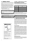
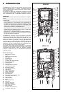
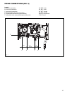
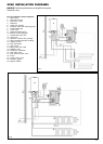
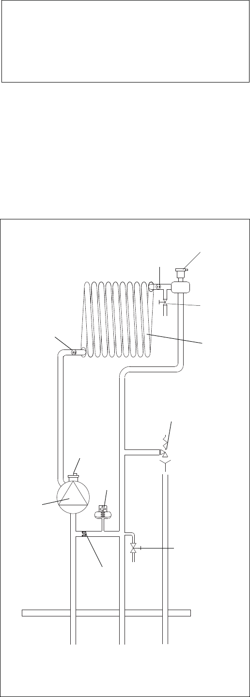
pressure
relief
valve
pump
return
temperature
sensor
main heat
exchanger
bottom
auto air
valve
pressure
switch
Heating
return
automatic
bypass
Heating
flow
drain
valve
flow
temperature
sensor
top
auto air
valve
manual air
release
pressure
relief valve
XPAK INTERNAL HYDRAULIC
CIRCUIT (FIG. 2)
Fig. 2
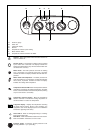
PRINCIPLE COMPONENTS
A fully integrated electronic control board featuring electronic
temperature control, anti-cycle control, pump over-run, actuator
anti-block function, self-diagnostic fault indicator, full air/gas
modulation.
- Radial aluminum heat exchanger.
- Electronic ignition with flame supervision
- Integral pump
- Fan
- Water pressure switch
- Condensate level sensor
- Pressure gauge
- Pressure relief valve
- Flue thermostat
- Flue sensor
- Blocked flue switch
MODE OF OPERATION (AT REST)
When the appliance is at rest and there are no requests for heating
or hot water, the following functions are active:
- 2-stage freeze protection system – the freeze protection system
protects the appliance against the risk of freeze damage. The
first stage enables activation of the pump should the tempera-
ture of the appliance fall to 43°F (6
o
C). Should the first stage
become active, the appliance will function on minimum +25%
power until it reaches 95°F (35
o
C).
- Anti-seize function – the anti-seize function enables the pump
to be energized for short periods, when the appliance has been
inactive for more than 24-hours.
MODE OF OPERATION
When there is a request for heat and/or hot water, via the
programmer/time clock and/or any external control, the pump and
fan are started, the fan speed will modulate until the correct signal
voltage is received at the control PCB. At this point an ignition
sequence is enabled.
Ignition is sensed by the electronic circuitry to ensure flame
stability at the burner. Once successful ignition has been
achieved, the electronic circuitry increases the gas rate to 75% of
the MAX Heating (set by the corresponding HTG trimmer) for a
period of 15 minutes. Thereafter, the boiler’s output will either
increase to maximum or modulate to suit the set requirement.
When the appliance reaches the desired temperature the burner
will shut down and the boiler will perform a three-minute post purge
(timer delay).
When the request for heat has been satisfied the appliance pump
and fan may continue to operate to dissipate any residual heat
within the appliance.
SAFETY DEVICES
When the appliance is in use, safe operation is ensured by:
- a water pressure switch that monitors system water pressure
and will de-activate the pump (when lockout condition is
reached), fan and burner should the system water pressure
drop below the rated tolerance;
- blocked flue switch that monitors flue pressure and will de-
activate the pump (when lockout condition is reached), fan and
burner should the flue pressure increase over the rated tolerance;
- fan speed sensor to ensure safe operation of the burner;
- a high limit thermostat that over-rides the temperature control
circuit to prevent or interrupt the operation of the burner;
- flame sensor that will shut down the burner when no flame signal
is detected;
- a sensor that interrupts the operation of the appliance if the
condensate pipe becomes blocked;
- a pressure relief valve which releases excess pressure from the
primary circuit;
- a flue sensor that controls the flue temperature continuously
checking to be right according the output;
- a flue thermostat that over-rides the temperature control circuit
to prevent or interrupt the operation of the burner.