


57
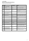
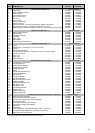
TECHNICAL DATA - LPG
Gas pressure XPak 85 XPak 120
Input - (0 - 2000 ft / 0 - 610 m) Btu/hr 25,600 - 87,000 27,300 - 119,500
kW 7.5 - 25.5 8.0 - 35.0
Input - (2000 - 4500 ft / 610 - 1375 m)
Btu/hr 25,600 - 82,900 27,300 - 114,300
kW 7.5 - 24.3 8.0 - 33.5
Gas supply pressure LPG in w. c. 11 11
kPa 2.75 2.75
Min. gas supply pressure LPG in w. c. 8 8
kPa 1.99 1.99
Max. gas supply pressure LPG in w. c. 13 13
kPa 3.24 3.24
Burner pressure (max-min) in w. c. 1.92-0.24 2.00-0.16
kPa 0.48-0.06 0.50-0.04
Rate
Gas Rate max LPG lbs/hr 4.02 5.55
kg/hr 1.82 2.52
Gas Rate min LPG lbs/hr 1.20 1.28
kg/hr 0.54 0.58
Emissions
CO2 setting % 10.0% 10.0%
NOx @ max ppm < 20 < 20
NOx @ min ppm < 15 < 20
CO @ max without air ppm < 200 < 200
CO @ min without air ppm < 40 < 35
Injector size
Injector LPG (E) - black coated Ø 0.15 inch (3.9 mm) 0.19 inch (5.0 mm)
BOILER FAN SPEEDS
The boiler fan speeds require to be checked and/or adjusted
prior to making any adjustments to the gas valve or if the main
PCB has been replaced.
ATTENTION
Gas type and boiler fan speed (output) must be set according to
the specific appliance specification. Raypak accepts no
responsibility if the gas type and/or fan speed is not correctly
adjusted according to the respective specification as detailed on
the boiler data badge.
ADJUSTING GAS PRESSURE
The gas pressure can not be adjusted as the boiler is equipped
with a pneumatic gas valve.
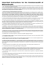
CHECKING/ADJUSTING THE APPLIANCE FAN SPEEDS
Move the selector switch to the OFF position and remove the
3-selector knobs.
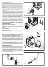
ABSOLUTE MAX FAN SPEED
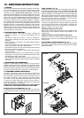
Locate the MAX trim pot (Fig. 2) and gently adjust clockwise or counter
clockwise to achieve the correct fan speed (see table below).
NOTE
The display shows the fan RPM in multiples of 1000, i.e. 2.5 = 2500RPM.
ABSOLUTE MIN FAN SPEED
Locate the MIN trim pot (Fig. 2) and gently adjust clockwise or
counter clockwise to achieve the correct fan speed (see table below).
NOTE
The display shows the fan RPM in multiples of 1000, i.e.
2.5 = 2500RPM.
IGNITION FAN SPEED
ATTENTION
Do this operation only after the adjusting of absolute max and
min fan speed.
Locate the IGN trim pot (Fig. 2) and gently adjust clockwise or
counter clockwise to achieve the correct fan speed (see table below).
NOTE
The display shows the fan RPM in multiples of 1000, i.e.
2.5 = 2500RPM.
HEATING FAN SPEED
Locate the HTG trim pot (Fig. 2) and gently adjust clockwise or
counter clockwise to achieve the correct fan speed (see table
below).
NOTE
The display shows the fan RPM in multiples of 1000, i.e.
2.5 = 2500RPM.
HTG
TMR
MIN
MAX
CO
IGN
Fig. 2
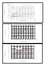
FAN SPEED (rpm) TABLE
MODEL MAX MIN HTG IGN
XPak85 5,700 1,900 5,700 3,700
XPak120 5,400 1,400 5,400 3,700
ADJUSTING THE GAS VALVE
THE GAS VALVE MUST BE SET-UP OR ADJUSTED WITH THE
AID OF A PROPERLY CALIBRATED FLUE GAS ANALYZER.
CHECKING THE CO2 AND ADJUSTING THE GAS VALVE
THE GAS VALVE MUST BE SET-UP OR ADJUSTED WITH THE
AID OF A PROPERLY CALIBRATED FLUE GAS ANALYZER.
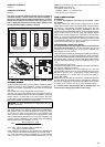
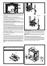
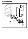
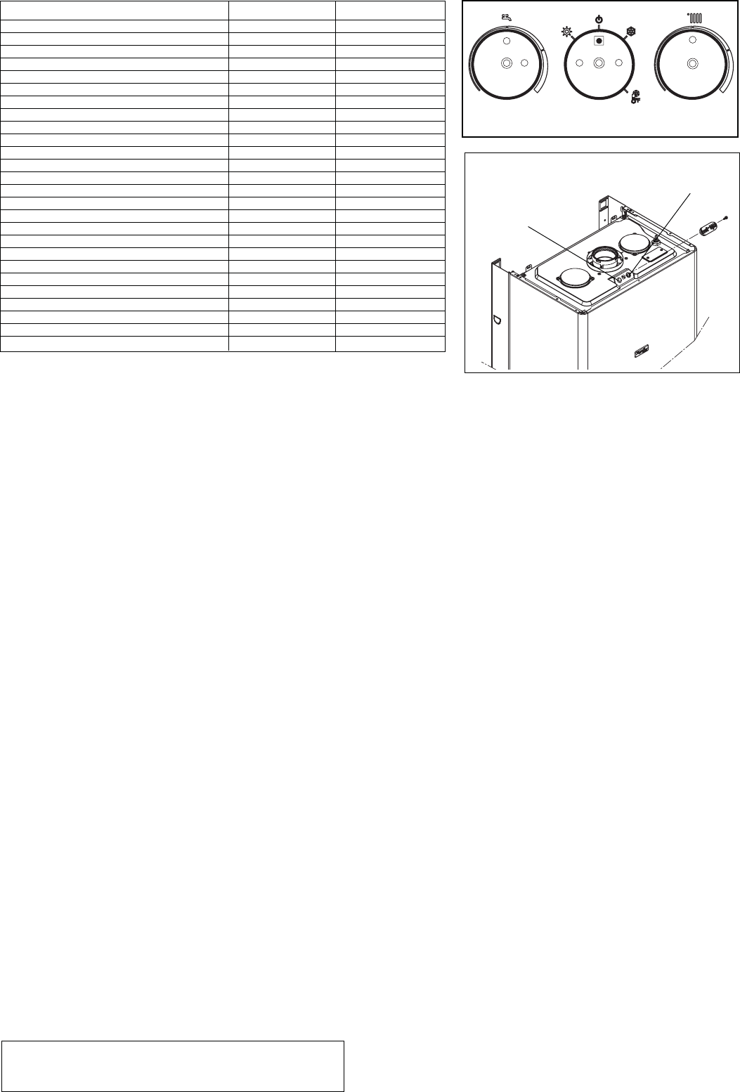
Isolate the boiler from the electrical supply and remove the
appliance casing. Set the flue gas analyzer to read CO2 and insert
the probe into the flue analysis test point (A-air, B-flue Fig. 3).
Restore the electrical supply to the boiler and switch the boiler to
the OFF mode. To adjust the gas valve you must first ensure that
the fan speed potentiometers (trim pots) have been set correctly.
Remove the 3-selector knobs, locate and press the CO button).
The appliance will now operate in CO mode for approximately 15-
minutes.
GAS VALVE MAXIMUM SETTING
Locate and gently turn the HTG trim pots until the maximum value
(max fan speed) is obtained and check that it corresponds with
the appropriate CO2 value (Maximum) for the respective boiler. If
the CO2 reading is correct, proceed to gas valve minimum setting.
However, If the CO2 reading is incorrect, the maximum gas
pressure must be adjusted as follows:
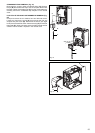
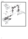
- Using a suitable screwdriver, very slowly turn the maximum
adjustment screw (Fig. 4) – clockwise to decrease, counter
clockwise to increase – until the correct value is displayed on
the CO2 analyzer (allow time for the analyzer to stabilize).
GAS VALVE MINIMUM SETTING
Locate and gently turn the HTG trim pot until the minimum value
(min fan speed) is obtained and check that it corresponds with
the appropriate CO2 value (Minimum) for the respective
appliance. If the CO2 reading is correct, rotate the HTG trim pot
until the correct value is obtained for the respective appliance
(see fan speed table) and proceed.
However, If the CO2 reading is incorrect, the minimum gas
pressure must be adjusted as follows:
- Using a suitable screwdriver, very slowly turn the minimum
adjustment screw (Fig. 4) – clockwise to increase, counter
clockwise to decrease - until the correct value is displayed on
the CO2 analyzer (allow time for the analyzer to stabilize).
INSTALLATIONS AT ELEVATION
Rated inputs are suitable for up to 4,500 ft elevation (see technical
data table). Consult the factory for installations at altitudes over
4,500 ft above sea level. No hardware changes are required to the
boilers for installations up to 10,000 ft (adjustments may be required).
COMPLETION
On completion of the combustion analysis check and/or any gas valve
adjustment, set the HTG trim pot to the corresponding value as detailed
in the fan speed table. Reattach the 3-selector knobs. Remove the test
probe from the test point and reattach the sealing screws and/or cap.
Fig. 3
A (air)
B (flue)