


24
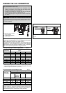
COMBUSTION AIR AND
VENTILATION OPENINGS
Provisions for combustion and ventilation air must be made in
accordance with section 5.3, Air for Combustion and Ventilation,
of the National Flue Gas Code, ANSI Z223.1, or Sections 7.2, 7.3
or 7.4 of CAN/CGA B149, Installation Codes, or applicable
provisions of the local building codes.
CAUTION: BOILER DAMAGE AND OPERATIONAL
FAILURES !
Due to insufficient or lacking openings for combustion air
and/or ventilation of the boiler room. Provisions for
combustion air and ventilation are always required,
regardless whether the combustion air is taken from the
outside (sealed combustion) or inside (room air for
combustion). Insufficient ventilation of the boiler room can
lead to high air temperatures.
This can result in boiler damage.
– Make sure that intake and exhaust openings are sufficiently
sized and no reduction or closure of openings takes place.
– When the problem is not resolved, do not operate the boiler.
– Please note these restrictions and its dangers to the operator
of the boiler.
WARNING: BOILER DAMAGE !
Due to contaminated air.
– Boiler must be clear and free from combustible materials,
gasoline and other flammable vapors and liquids, and
corrosive liquids and vapors. Never use chlorine and
hydrocarbon containing chemicals (such as spray
chemicals, solution and cleaning agents, paints, glues etc)
in the vicinity of the boiler.
– Do not store and use these chemicals in the boiler room.
– Avoid excessive dust formation and build-up.
NOTICE:
When one expects contaminated combustion air
(near swimming pools, chemical cleaning operations and
hair salons), sealed combustion operation is recommended.
DANGER: FIRE DANGER !
Due to flammable materials or liquids.
– Do not store flammable materials and liquids in the
immediate vicinity of the boiler.
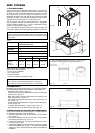
All Air from Inside the Building (room air)
The room shall be provided with two permanent openings
communicating directly with an additional room(s). The total input
of all gas utilization equipment installed in the combined space
shall be considered in making this determination. Each opening
shall have a minimum free area of 1 square inch per 1,000 Btu per
hour of total input rating of all gas utilization equipment in the
confined space, but no less than 100 square inches. One opening
shall commence within 12 inches (305 mm) of the top, and one
opening shall commence within 12 inches (305 mm) of the bottom
of the enclosure. The minimum dimension of air openings shall be
not less than 3 inches (75 mm).
All Air from Outdoor (sealed combustion)
The room shall be provided with two permanent openings, one
commencing within 12 inches (305 mm) from the top, and one
commencing within 12 inches (305 mm) from the bottom of the
enclosure. The openings shall communicate directly, or by ducts,
with the outdoors or spaces (crawl or attic) that freely communicate
with the outdoors.
The minimum dimension of air openings shall be no less than 3
inches (75 mm).
1. Where directly communicating with the outdoors, each open-
ing shall have a minimum free area of 1 square inch per 4,000
Btu/hr of total input rating of all equipment in the enclosure.
2. Where communicating with the outdoors through vertical ducts,
each opening shall have a minimum free area of 1 square inch
per 4,000 Btu/hr of total input rating of all equipment in the
enclosure.
3. Where communicating with the outdoors through horizontal
ducts, each opening shall have a minimum free area of 1 square
inch per 2,000 Btu/hr of total input rating of all equipment in the
enclosure.
4. Where ducts are used, they shall be of the same cross-sectional
area as the free area of the opening to which they connect.
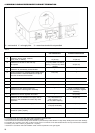
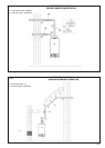
INSTALLATION OF THE EXHAUST
AND AIR INTAKE SYSTEM
NOTICE:
Consult local and state codes pertaining to special
building code and fire department requirements. Adhere to
national code requirements.
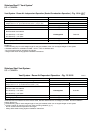
NOTICE:
Observe the listed maximum lengths of vent system,
which are boiler model dependent. The maximum permissible
lengths are listed in the main specification Tab. 5.
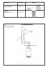
An optional concentric vent/air intake body can be used for the
installation of a vertical venting system as well as for a horizontal
venting system. The concentric vent/air intake body can be ordered
through Raypak Inc.
The boiler can also be operated with separate air intake and
exhaust piping.
The termination shall be at least 4 ft (1220 mm) for the U.S. and
6ft. (1830 mm) for Canada away from a gas utility meter, service
regulator or the like (for room air applications only).
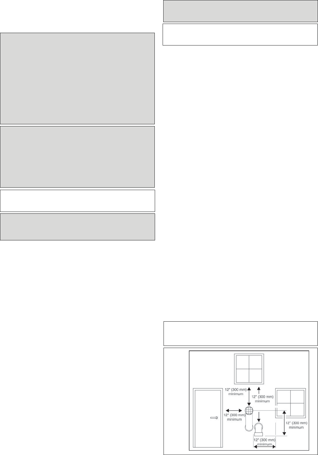
The termination shall terminate at least 4 ft (1220 mm) below, 4 ft
(1220 mm) horizontally from, or 1 ft (305 mm) above any door,
window, or gravity air inlet into any building.
Vent must be at least 12 inches (305 mm) above grade, anticipated
snow line or roof surface (Canada 18” (457 mm) minimum).
Vent termination must be at least 7 ft (2135 mm) above a public
walkway (see Fig. 20).
Vent must be 3 ft (915 mm)above any forced air intake within 10
ft (3050 mm) (see Fig. 20).
Do not extend exposed vent pipe outside the building beyond
recommended distance. Condensate could freeze and block vent pipe.
Vent should terminate at least 3 ft (915 mm) away from adjacent
walls, inside corners and below roof overhang.
It is not recommended to terminate vent above any door or
window, condensate can freeze causing ice formations.
Do not use chimney as a raceway if another boiler or fireplace is
vented into or through chimney.
All vent pipes must be glued, except for the flue gas adapter which
is fix into place and the first connection to the flue gas adapter.
Installed you can slide the pipe onto the adapter, properly supported
and the exhaust pipe must be pitched a minimum of a ¼ inch per
foot back to the boiler. This allows the condensate to drain away.
NOTICE:
- Do not use cellular core pipe.
- A minimum clearance of 4 feet horizontally from and in no case
above and below, unless a 4-foot horizontal distance is
maintained, from electric meters, gas
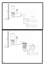
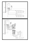
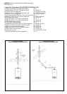
Below are approved examples of vertical and horizontal venting
installation
- Place pipe supports every 5 feet (1525 mm) of horizontal run,
beginning with support near boiler.
- Periodic cleaning of the vent terminal and air-intake screens is
mandatory.
- The minimum covering wall thickness is 1" (25 mm).
- The maximum covering wall thickness is 16" (406 mm).
- For Direct venting properly reassembele and reseal the vent
and air-intake systems.
CAUTION: Vent connectors serving appliances vented by
natural draft shall not be connected into any portion of
mechanical draft systems operating under positive pressure.
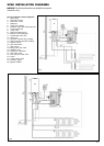
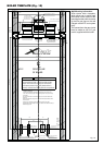
Fig. 15A