


25
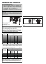
2. BOILER SUPPLY
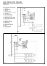
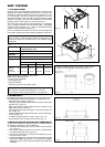
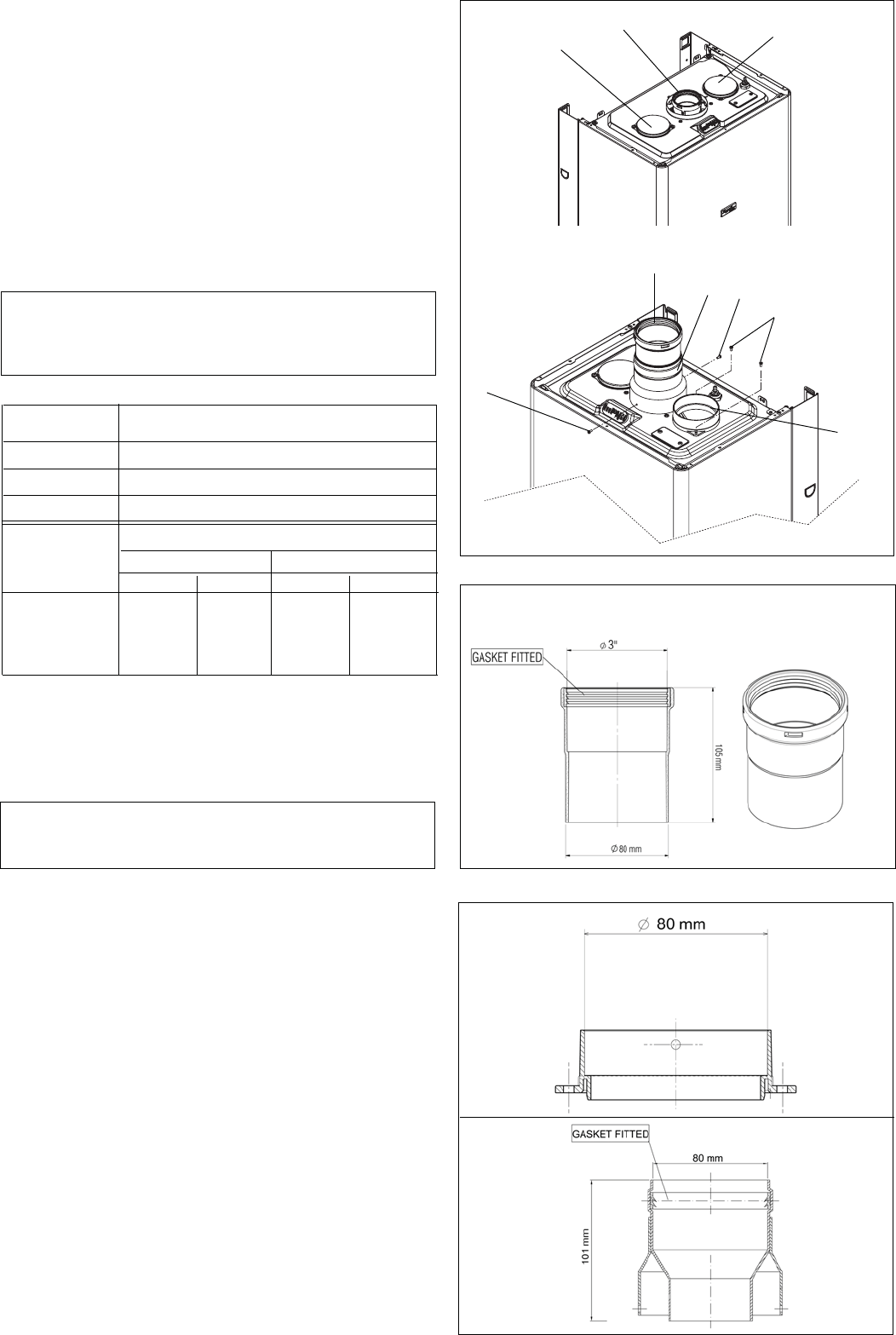
XPak boilers are supplied with the following vent components and they
are certified together with the XPak boiler as a constructional unit.
- 60/100 mm vent exit (Fig. 16 pos. 1)
- Left side intake air (factory sealed with two screws) for two pipes
solutions (Fig. 16 pos. 2)
- Right side intake air (factory sealed with two screws) for two
pipes solutions (Fig. 16 pos. 3)
- Vent adaptor for two pipes vent system – 80 mm dia exit (Fig. 16
pos. 5) (Fig. 19)
- Intake air adaptor for two pipes vent system – 80 mm dia exit (Fig.
16 pos. 6) (Fig. 18)
- 3” adaptor (inside diameter 3”) (Fig. 16 pos 4, Fig. 17)
- Paper template to fix the boiler and the flues (Fig. 15)
Fig. 16
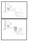
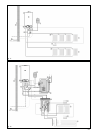
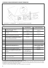
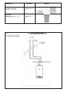
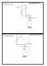
3. INSTALLATIONS OF SUPPLIED VENT COMPONENTS
In the case of installations using two pipes or room dependent air
the following instructions must be observed.
1. Install the vent adapter (Fig. 19) to the boiler vent connection
(Fig. 16 pos. 1)
2. Use the two supplied screws to ensure the closing between
the adapter and boiler (Fig. 16 pos. 5)
3. Insert the 3” adapter (Fig. 17) into the vent adapter (Fig. 19) in
the case using 3” vents
4. Install the air adapter (Fig. 18) to the boiler air connection (choose
right or left installation (Fig. 16 pos. 2 - 3), using the two supplied
screws (Fig. 16 pos. 6) in the case of two pipes, room sealed vent
installation.
Fig. 19
Fig. 17
Fig. 18
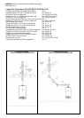
VENT SYSTEMS
1. FLUE GAS SYSTEM
Raypak coaxial PP (Polypropylene/Aluminium) concentric flue
gas/fresh air systems, Raypak coaxial Alu/Alu concentric flue
gas/fresh air systems and two-pipe aluminum systems for room
air independent operation (sealed combustion) and air
dependent operation and side wall venting are tested to ANSI
ANSI Z21.13b 2007 – CSA 4.9b 2007 standards and are certified
together with the XPak boiler as a constructional unit.
The XPak boiler may also be vented vertically or horizontally,
using a metallic AL29-4C
®
special stainless steel - Suggested
sources: ProTech System Inc., or room air dependent venting
system (UL/ULC listed for category IV).
For a more detailed description of the direct vent and single-wall
vent system, please refer to the following installation Instructions.
Always follow XPak Installation Instructions.
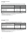
Select vent material based on
- Country of the installation
- Vent configuration
- Preferred material
- Necessary maximum equivalent length
FasNseal
stainless steel vent
Country US + CANADA
Diameter 3”
Material Stainless steel
Single wall Maximum Equivalent Length 3” (80 mm)
Tab. 5
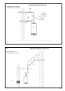
NOTICE:
Brick or masonry surfaces directly behind the horizontal vent
termination should be protected with a rust-resistant sheet
metal plate.
NOTICE:
The minimum covering wall thickness is 1” (25 mm)
The maximum covering wall thickness is 16” (406 mm)
4
5
6
A
B
A
1
2
3
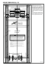
1 Gasket in EPDM (peroxide) -58°F (-50°C) – 302°F (150°C)
2 Adapter in PP (polypropylene) male/female 80 mm > 3”
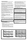
De-rate less 5%De-rate less 2%
XPak 85
XPak 120 XPak 85 XPak 120
Horizontally/
vertically
vented
(air+flues)
40+40ft
16+16
130+130 115+115
12+12m
5+5
40+40 35+35