


35
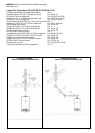
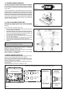
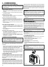
4. CASING REMOVAL (Fig. 33)
To gain internal access to the appliance you must first remove the
casing, proceed as outlined below:
- remove the 3 screws (B) located at the Left/Right/Front of the
underside of the casing
- lift the casing upward to disengage it from the top locating
hooks and then remove
- store the casing and screws (B) safely until required. Re-fit in
the reverse order.
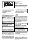
5. APPLIANCE TERMINAL BLOCK
The appliance terminal block is located on the rear of the control
panel. Remove the casing. Gently pull the control panel forwards
and down. Locate the terminal block cover (see Fig. 34).
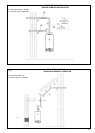
NOTICE:
The appliance comes with a factory installed jumper
for room thermostat connection to allow basic operation of
the boiler via the mode selector switch. If it is anticipated that
external controls will be required please refer to the wiring diagrams
(remove room thermostat jumper if there is the remote control
installed on the low voltage terminal strip - M4 Fig. 35).
External connection board connections
Make all electrical connections inside the external connection
box.
- Open the cover of the external connection box (Fig. 34).
Connecting incoming power
The boiler must be electrically grounded in accordance with local
codes, or in absence of local codes, with the National Electrical
Code, ANSI/INFPA 70 and/or the CSA C22.1, Electrical Code.
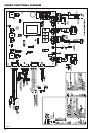
Boiler terminal strip (Fig. 35)
The XPak terminal strip is divided in two separated area: low
voltage and high voltage area.
The high voltage area is dedicated to:
- connections incoming power: ground neutral line, a fuse (4A)
is factory fit directly on the terminal strip, 3 pins - M3
- connection for 3-way DHW valve (field supplied) 3 pins - M3a
The low voltage area is dedicated to:
- external sensor (2 pins - M4)
- remote control (2 pins - M4)
- DHW tank sensor (2 pins - M4a)
- DHW tank thermostat (2 pins - M2)
- Room thermostat (2 pins - M4a) factory jumper
- External alarm (3 pins - M3b) factory jumper
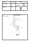
6. CONNECTING THE ELECTRICAL SUPPLY (120V)
Unhook and remove the terminal block cover (120V). Pass the
cable through the cable anchorage point on the control panel.
Pass the cable through the Strain Relief Bushings (field supplied)
(Fig. 39).
The boiler is equipped with 4 holes in the lower support .
- Chose the circle holes in the case of using Heyco-Flex Metallic
(SR 7K-2) (Fig. 39 ref. 2).
- Chose the non-circle holes in the case of using Strain Relief
Bushings (1/2” HFC-Z 1/2) (Fig. 39 ref. 1).
Connect the supply cable wires (LIVE, NEUTRAL & GROUND) to
their corresponding terminals (L, N & G) on the appliance - 120V -
terminal block. When connecting the GROUND wire, ensure that
it’s left slightly longer (about 1 in (20 mm)) that the others, this will
prevent strain on the GROUND wire should the cable become
taut.
Do not remove the link wire unless additional external controls
are to be fitted. The securing screw on the cable anchorage
should now be tightened (Fig. 37). This must be done before the
control panel is reinstalled in the upright position. The appliance
casing, screws and lower cover can now be reinstalled.
NOTICE: It is the installer’s responsibility to ensure that the
appliance is properly grounded.
Raypak cannot be held responsible for any damages or
injuries caused as a result of incorrect ground wiring.
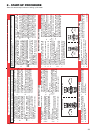
7. EXTERNAL WIRING
The appliance comes with a factory installed room thermostat
link to allow basic operation of the boiler via the mode selector
switch. If external controls are to be added to the system, they
must be connected to the appliance as shown in the following
diagrams. For advice on controls that are not featured in this
book, please contact Raypak technical department.
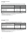
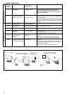
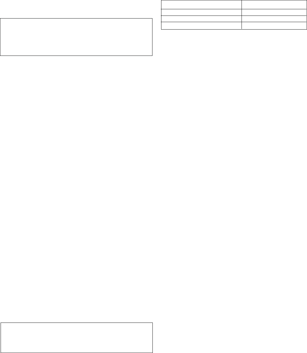
8. EXTERNAL WIRING LIMITATIONS
Any external wiring must remain within the limits as detailed in
the table below
9. CONNECTING THERMOSTAT
1. Connect room thermostat or end switch, terminal strip is 24V
(Fig. 35 ref. M4a)
2. Install thermostat on inside wall away from influences of drafts,
hot or cold water pipes, lighting fixtures, television, direct
sunshine or fireplaces.
10. OTHER DEVICES
Contact Raypak technical department should you require more
specific information on the suitability of a particular control. Further
guidance on the recommended practice for the installation of
external controls, can be found.
IMPORTANT
- The boiler must always be supplied with a permanent 120V
electrical supply.
- Always remove the link on M4a terminal strip on the appliance
low voltage 24V terminal strip whenever additional controls
are connected to the appliance.
- Do not connect any controls or auxiliary equipment to the 24V
terminal strip, other than that approved/supplied by the
manufacturer.
CONNECTION MAX. LENGTH
Outdoor air sensor 100 ft (30 metres)
Room thermostat 100 ft (30 metres)
Remote control connection 100 ft (30 metres)