


43
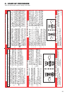
10 - START-UP AND OPERATION
XPak wall-mounted condensing boiler is designed for the
production of heating and domestic hot water if a storage tank is
connected.
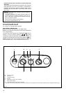
The control panel contains the main boiler control and manage-
ment functions.
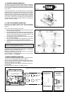
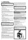
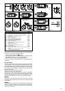
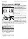
1. SWITCHING ON THE APPLIANCE
Switch on the boiler as follows:
- Open the gas tap under the boiler by turning it
counterclockwise (Fig. 46)
- Turn on the general switch of the system and then, after
lowering the flap, turn the function selector to summer
,
winter
or winter tank temperature
F
(Fig. 54) depending
on the chosen operating mode.
Pump cycle mode
: when power is restored to the boiler and/
or the boiler is powered for the first time, the boiler will enter a 2-
minute purge cycle whereby only the pump will run for 15-seconds
then off for 15-seconds and will not “fire” until this period has
elapsed. To interrupt the purge cycling remove the knob of the
main selector switch and press the CO button (Fig. 59).
Off/reset
- Select this position when the boiler needs to be
reset or switched off.
Summer mode
- The domestic hot water function provided
by the water tank is activated. The display indicates the storage
tank temperature (only with the external water tank connected
with a sensor).
Winter mode
- The boiler produces hot water for heating
and, if connected to an external water tank, it provides domestic
hot w
ater. The display indicates the boiler flow temperature.
Winter mode tank temperature
F
- The boiler produces
hot water for heating and, if connected to an external water tank
with a sensor
, it provides domestic hot water. The display indicates
the storage tank temperature.
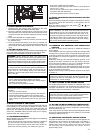
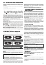
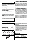
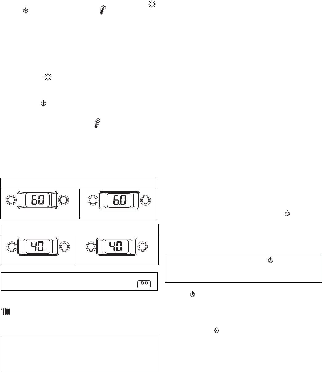
2. HOW TO READ THE DISPLAY TEMPERATURE
● (dot in the middle)= means hundred (Fig.43)
● (dot on RIGHT side)= means DHW mode (Fig. 44)
example:
NOTICE:
For temperature over 199°F (93°C) the display shows
.
Adjusting heating water temperature
To adjust the heating water temperature turn the knob marked
(Fig. 50) clockwise to increase and counterclockwise to
decrease.
When turning the knob, the required temperature automatically
appears on the digital display.
NOTICE: Depending on the type of system, it is possible to
pre-select the suitable temperature range:
- standard systems 104-176°F (40-80°C)
- floor systems 68-113°F (20-45°C).
For further details, consult the “Boiler configuration” (Fig. 61)
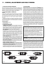
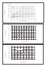
3. ADJUSTING HEATING WATER TEMPERATURE WITH
AN OUTDOOR PROBE CONNECTED
When an outdoor probe is connected, the value of the delivery
temperature is automatically chosen by the system which rapidly
adjusts ambient temperature to the changes in outdoor tempe-
DHW mode
40°F 140°F
60°F 160°F
Heating mode
Fig. 43
Fig. 44
rature. To increase or decrease the temperature with respect to
the value automatically calculated by the PCB, turn the heating
water selector (Fig. 50) clockwise to increase and
counterclockwise to decrease.
Adjustment settings range from comfort levels - 5 to + 5 which are
indicated on the digital display when the knob is turned.
4. ADJUSTING DOMESTIC HOT WATER TEMPERATURE
(IF A STORAGE TANK WITH SENSOR AND 3-WAY
VALVE IS INSTALLED)
When turning the knob, the required temperature automatically
appears on the digital display. The domestic hot water adjustment
ranges lies between 95°F (35°C) and 140°F (60°C). When
choosing the temperature, both for heating and domestic hot
water, the display shows the value being selected. About 4
seconds after the selection has been made, the modification is
recorded and the display returns to the delivery or domestic hot
water temperature read by the probe. Priority is always given to
DHW production.
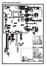
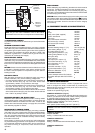
The boiler setting depends from the jumper JP position (Fig. 63).
- CASE A (factory set) heating only + external water tank with
thermostat adjustment inapplicable - jumper in position 3
- CASE B heating only + external water tank with sensor - to
adjust the temperature of the domestic hot water in the water
tank, turn the temperature selector clockwise to increase and
counterclockwise to decrease - jumper in position 2.
5. WORKING THE BOILER
If a programmable timer or ambient thermostat are mounted,
these must be switched on and adjusted to higher than ambient
temperature in order to allow the boiler to start.
The boiler remains on standby until the burner ignites as a result
of a demand for heat. The green indicator LED (B, Fig. 52), located
on the left-hand side of the panel, lights up to indicate the flame
is present. The boiler continues to work until the selected
temperatures have been reached. It then returns to “stand-by”
while displaying delivery temperature.
In the event of a starting or operating fault, the boiler performs a
“SAFETY STOP”: the green indicator LED on the control panel
goes out, a fault code flashes on the display (Fig. 53) and a red
indicator LED (D) lights up in the event of a shutdown. To identify
the fault codes and reset the boiler, consult the “Indicator LEDs
and faults” section.
6. RESET FUNCTION
To reset the boiler, turned the function selector to
(Fig. 54) then
move it to the required position and check that the red indicator
LED has gone out.
At this point, the boiler starts automatically if correct operating
conditions have been restored; when the burner ignites, the green
indicator led lights up and the digital display indicates the
instantaneous operating temperature.
NOTICE: Simply turning the selector to
does not reset the
boiler.
If the boiler continues not to work, call your local Service
Technician.
In normal operating conditions, when the function selector is
turned to
, the digital display indicates “- -” (Fig. 55) unless the
anti-freeze phase (AF - Fig. 56) is in progress or the combustion
analysis function is activated (CO - Fig. 58).
7. SWITCHING OFF
For short absences (weekends, brief journeys, etc.) turn the
function selector to
OFF/RESET.
As the boiler remains powered with the gas tap open, it is
protected by the following systems:
- Freeze protection:
Heating
The function starts if the temperature measured by the flow
sensor falls below 43°F (6°C). In this mode, a heat demand is
generated and the burner ignites at minimum power. This is
maintained until the temperature of the water flow reaches
95°F (35°C).