


15
PACKAGING AND TRANSPORTATION
1. SCOPE OF DELIVERY
The boiler is delivered fully assembled.
- When receiving the delivery, check if the packaging is intact.
- Check that all the items listed in Table 2 are included in the
delivery.
2. TRANSPORTING THE BOILER
CAUTION:
The boiler may be damaged when it is improperly
secured.
- Only transport the boiler using the right transportation
equipment, such as a handtruck with a fastening belt or
special equipment for maneuvering steps.
- During transportation the boiler must be secured on the
transportation equipment to prevent it from falling off.
- Protect all parts against impacts if they are to be
transported.
- Observe the transportation markings on the packaging.
- Packaged boilers must always be lifted and carried to
their destination by two people, or you must use a handtruck
or special equipment to transport them to their destination.
- Transport the boiler to the room where it is to be installed.
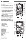
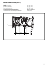
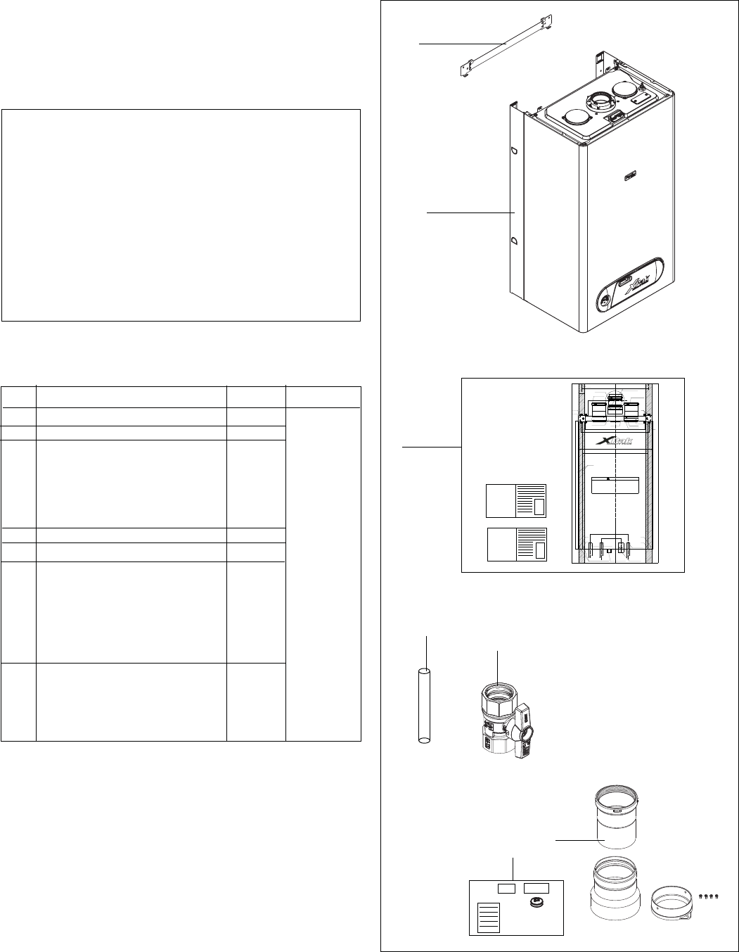
Pos. Parts Quantity Packaging
1 Boiler with casing 1 1 box
2 Wall bracket 1
3 Technical documents 1
including:
- User’s Instructions
- Installation Instructions
- Wall Mounting Template
4 Top manual air vent drain pipe 1
5 Gas shut off valve 1
6 Flue gas adaptors including: 1
- vent adaptor for two pipes
vent system
- intake air adaptor for two pipes
- 3” adaptor
- 4 screws
7 LPG conversion kit 1
- injector black coated
- LPG sticker
- LPG conversion labelling
- Conversion instructions
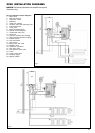
3. BOILER BOX CONTENT (Table 2)
1
2
5
6
4
3
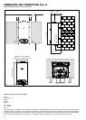
5.90"
3.35" 1.38"
XPak 120 - 17.81"
XPak 85 - 15.75"
14.17"
16.25"
C/C16"
1.5"
3.54"
inside 3"
inside 3.15"
4,53"Hole for 60/100mm coaxial vent
30.71" Boiler height
3.14"
XPak
120
XPak
85
XPak
85
XPak
120
Ø1/4" holes for earthquake restraint (2 places)
IN 3/4"
NPT male
OUT 3/4"
NPT male
Gas shut off valve (supplied)
3/4" NPT female
Condensate piping flexible (supplied)
4/5" female
Boiler outline
Boiler bracket
(supplied)
Ø1/4" holes
for 5/16" lag
screws (4 places)
XPak
120
XPak
85
Inlet air either right or left
3" vent adaptor (supplied)
3" inlet air adapter (not supplied)
Exhaust vent adapter (supplied)
Screw (2x) (supplied)
Screw (2x) (supplied)
Screw (2x) (fitted)
Inlet air adapter (supplied)
Wall stud
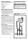
CENTER LINE
OF BOILER
L
C
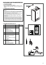
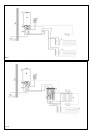
Ensure there is adequate clearances for mounting the boiler (details given in
installation instructions).
The wall mount bracket is designed for a stud spacing of 16 inches from
center. For other stud spacing a solid mounting surface must be provided by
the installer.
Do not mount the boiler to a hollow wall. Be sure to mount the boiler to the
studs only.
Mount the wall bracket using 4 5/16" lag screws. Ensure the bracket is level
when mounted.
Extreme care is needed to ensure the bolts are secured in the studs.
Hang the boiler on the bracket and secure the bottom of the boiler with two (2)
additional lag screws.
This boiler is heavy and awkward to lift. It is
recommended and safer to install the boiler with two
people. Use caution as to not drop this boiler which
could cause personal injury. Verify that the boiler is
securely mounted before leaving the boiler unsupervised.
WARNING
Pressure relief valve drain
3/4" NPT female
Fig. 5
7
Refer to Fig. 5 for Boiler box contents.