31
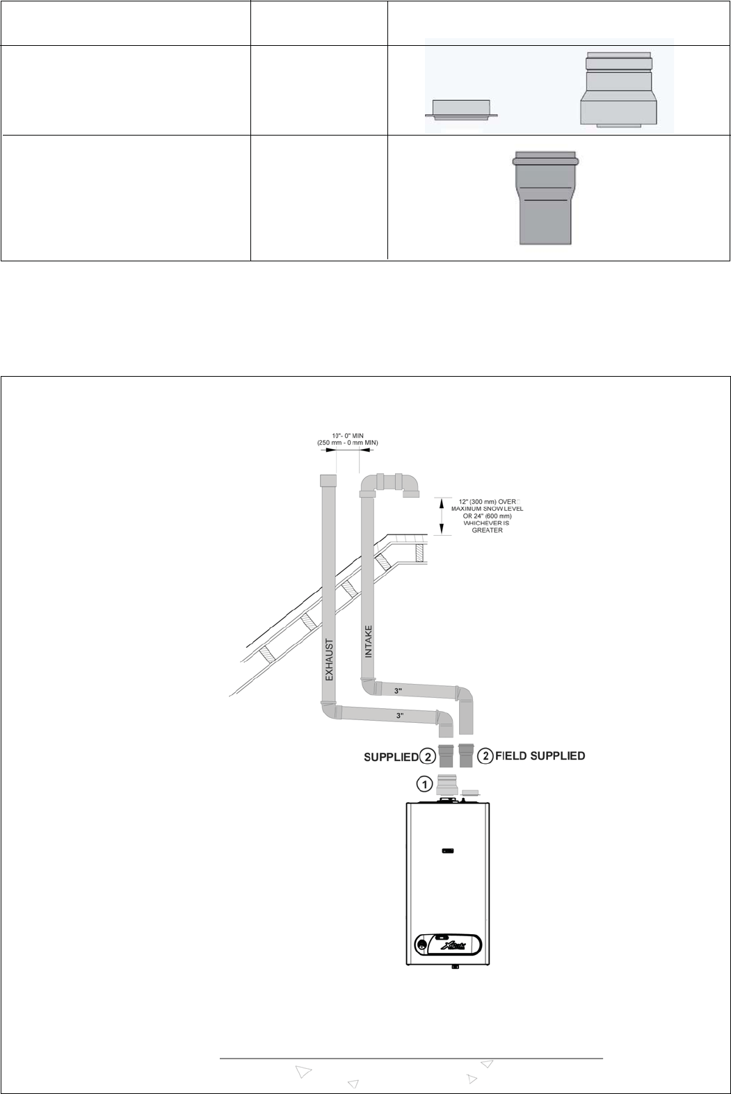
Fig. 29
a = total intake length = INTAKE
b = total flue length = EXHAUST
DESCRIPTION DIAGRAM DRAWING
P/N 013040
Two pipes vent adaptors Fig. 29-30-31-32
(included with the boiler) Pos. 1
P/N 013040
adaptor 80 mm > 3” Fig. 29-30-31-32
(included with the boiler 1 pcs) Pos. 2
TWO PIPES SINGLE WALL
SEALED COMBUSTION OPERATION


