


36
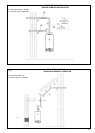
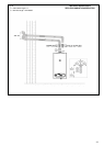
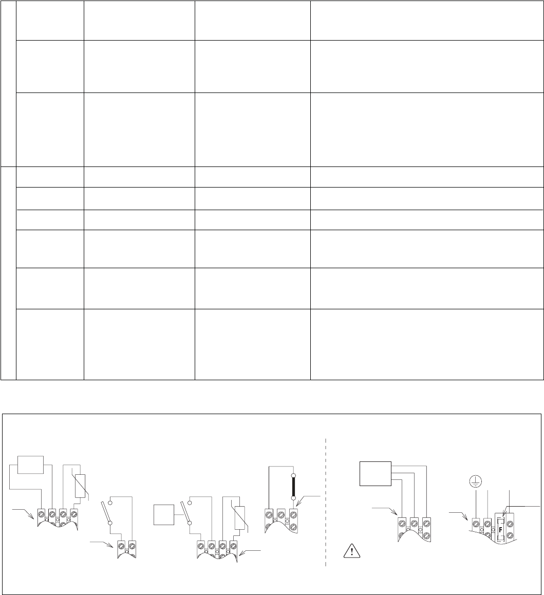
REMOTE CONTROL
EXTERNAL
SENSOR
0T+
M4
-t°
M2
TANK
THERMOSTAT
V
ROOM
THERMOSTAT
(jumper when
not used)
TANK
SENSOR
-t°
M4a
M3b
M3a
M3
UNDERFLOOR HEATING LIMIT
THERMOSTAT OR
CONDENSATE PUMP ALARM
(jumper when not used)
LOW VOLTAGE
HIGH VOLTAGE
120V
N
L
F=
fuse 4AF
PCB fuse=4AT
Cod. 20003227
3W
BLUE (COMMON)
BROWN (CLOSED)
BLACK(OPEN)
Fig. 35
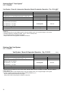
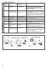
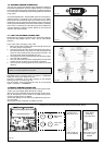
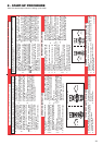
11. TERMINAL STRIP DETAILS
Terminal Description Technical Indications
strip specifications
reference
M3 Main supply 120 VAC – 60 Hz The main supply cable must be anchored to the
boiler frame (Fig. 39) and pass through the
strains relief (field supplied). Cable as specified in
the electrical supply.
M3a 3-way valve:
Connections for DHW Model: Honeywell VC6011 (actuator) + VCZMK6000
external 3-way valve 120 VAC – 60 Hz (Cartridge valve)
The 3-way valve cable must be anchored to the boiler
frame (Fig. 39) and pass through the strains relief (field
supplied) (Fig. 39). Cable as specified in the electrical
supply.
M4 Outdoor sensor 12 K Ohm B3760
M4 Remote control Open therm plus protocol Only Raypak Part No. 013073
M4a Room thermostat 24 VDC Volt free (Jumper when not used)
M4a Tank sensor 10 K Ohm B3435 Immersion type.
for DHW If the boiler is installed with a tank sensor, the Jumper
on the PCB must be in position 2 (Fig. 61)
M2a Tank thermostat On/off (NO) Volt free
for DHW If the boiler is installed with a tank termostat, the
Jumper on the PCB must be in position 3 (Fig. 61)
M3b Under-floor heating limit On/off (NC) Volt free.
thermostat and condensate This is a generic input to lock out the boiler. Jumper when
(generic available alarm) not used). If the contact will be
open the alarm number 21
will appear on the display and the boiler is lock out
High voltage (Fig. 35)
Low voltage (Fig. 35)
Tab. 9