


53
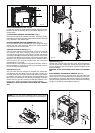
WATER PRESSURE SWITCH (Fig. 69)
Locate and remove the screw (I) from the water pressure switch.
Remove the wiring. Carefully remove the switch. Replace in the
reverse order.
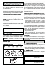
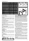
FLOW SENSOR (PRIMARY THERMISTOR) (Fig. 1)
Unclip and remove the air chamber front cover. Unclip the primary
thermistor from the flow outlet pipe. Disconnect thermistor electrical
plug. Replace in the reverse order.
RETURN SENSOR (RETURN THERMISTOR) (Fig. 1)
Unclip and remove the air chamber front cover. Unclip the return
sensor from the return inlet pipe. Disconnect sensor electrical
plug. Replace in the reverse order.
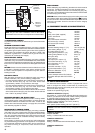
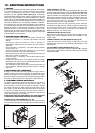
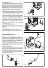
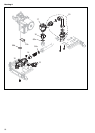
PRINTED CIRCUIT BOARD (Fig. 71)
Pull the control slightly forward and lower it. Push the clips (A)
and remove cover, after carefully taking note of all wiring
connections and jumper tag configurations; unhook and remove
connection block (B). Disconnect all wiring from the PCB, locate
and remove the PCB securing screws, remove the required PCB.
Replace in the reverse order ensuring that the position of the 3
control knobs are correctly aligned with the respective
potentiometers on the PCB.
Ensure that the correct jumper configuration has been made. It
will be necessary to check the functioning of the PCB is set for
the correct boiler type/application.
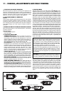
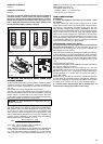
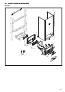
GAS VALVE (Fig. 72)
The gas valve must be changed as complete unit. Disconnect
the electrical plug and leads from the gas valve, slacken and
unscrew upper gas valve pipe, please note that the gas injector
is located in this upper part. Disconnect the compensation pipe
(C). Locate and remove the two retaining screws (D); locate and
remove the four gas valve retaining screws (E). Replace in the
reverse order. Check and adjust burner pressure settings.
WARNING, A GAS TIGHTNESS CHECK MUST BE CARRIED
OUT.
Fig. 70
Fig. 71
A
B
A
B
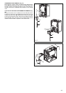
NOTICE: The gas valve sticker “WARNING: VALVE IS NOT FIELD
SERVICEABLE” means the valve can be adjusted but not disassembled.
E
E
C
XPak 85
D
E
E
C
XPak 120
D
Fig. 72
INJECTOR (Fig. 72)
Slacken and unscrew upper gas valve pipe; locate and remove
only two screws (D). Locate and remove the injector (F) inside
the pipe. Replace in the reverse order. Check and adjust burner
pressure settings.
WARNING, A GAS TIGHTNESS CHECK MUST BE CARRIED
OUT.
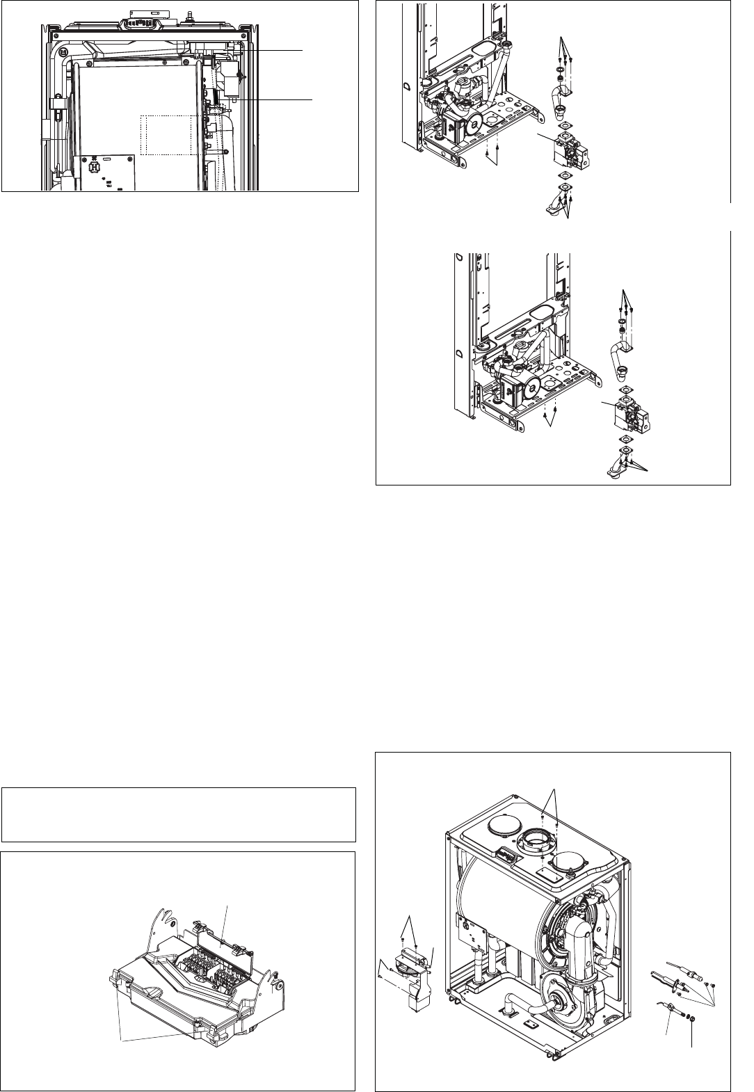
ELECTRODES & CONDENSATE SENSOR (Fig. 73)
Unclip and remove the air chamber front and right hand side
covers. Disconnect the electrode leads and ancillary wiring from
their respective connectors. Remove the retaining screws (A) for
spark and sensing electrodes and remove. Remove the retaining
nut (C) for condensate sensor (D) and remove.
Fig. 73
A
C
D
G
I
F
H