


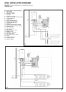

27
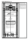
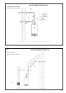
Fig. 24
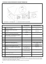
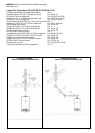
Fig. 23
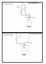
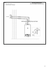
NOTICE:
The following illustrations are simplified conceptual
illustrations only.
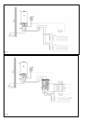
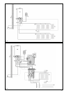
Legend for illustrations 23-24-25-26-27-28-29-30-31-32
Two pipes vent adaptors (included with the boiler) Pos. 1
Mounting Clip (set of 4) 3.94” (100 mm) for coaxial Pos. 2 (Fig. 24)
90° Elbow 3” (80 mm) single wall Pos. 2 (Fig. 25-26-27-28)
Adaptor 80 mm > 3” (included with the boiler 1 pcs) Pos. 2 (Fig. 29-30-31-32)
45° Elbow 3” (80 mm) single wall Pos. 3 (Fig. 25-26-28)
Vertical vent termination 3.28 ft (1 m) 3.94” (100 mm) coaxial Pos. 3
Straight Pipe 1.64 ft (0.5 m) 3” (80 mm) single wall Pos. 4 (FIg. 25-26-28)
Roof Flashing flat universal Pos. 4 (Fig. 23)
Straight Pipe 3.28 ft (1 m) 3” (80 mm) single wall Pos. 5
Straight Pipe 6.56 ft (2 m) 3” (80 mm) single wall Pos. 6 (Fig. 28)
Roof Flashing sloping universal Pos. 6 (Fig. 24)
45° Elbow 3.94” (100 mm) coaxial Pos. 7
Horizontal inlet air vent 2.82 ft (0.86 m) 3” (80 mm) single wall Pos. 8 (Fig. 25-26-27)
Straight Pipe 1.64 ft (0.5 m) 3.94” (100 mm) coaxial Pos. 8 (Fig. 24)
Adaptor for room air dependent operation Pos. 9 (Fig. 28)
Straight Pipe 3.28 ft (1 m) 3.94” (100 mm) coaxial Pos. 9 (Fig. 24)
90° Elbow 3.94” (100 mm) coaxial Pos. 10 (Fig. 24)
Mounting Clip (set of 4) Pos. 10 (Fig. 25-26-27-28)
Vertical vent termination 3” (80 mm) single wall Pos. 11
VERTICAL COAXIAL
SEALED COMBUSTION OPERATION
VERTICAL COAXIAL
SEALED COMBUSTION OPERATION