


2 - 47
2 MULTIPLE CPU SYSTEM
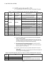
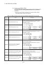
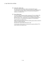
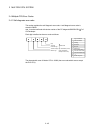
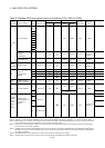
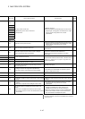
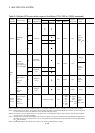
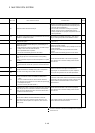
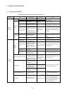
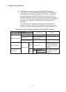
Error code Error contents and cause Corrective action Remark
1000
1001
1002
1003
1004
1005
1006
1007
1008
1009
Run-away or failure of main CPU
(1) Malfunctioning due to noise or other reason
(2) Hardware fault
(1) Measure noise level.
(2) Reset and establish the RUN status again. If the same error is
displayed again, this suggests a CPU hardware error. Explain
the error symptom and get advice from our sales
representative.
1105 Shared CPU memory fault in the CPU.
(1) Measure noise level.
(2) Reset and establish the RUN status again. If the same error is
displayed again, this suggests a CPU hardware error. Explain
the error symptom and get advice from our sales
representative.
1300
There is an output module with a blown fuse.
Check ERR. LED of the output modules and replace the module
whose LED is lit.
1401
There was no response from the motion module or intelligent
function module during initial communications.
The Motion dedicated module, the intelligent function module, the
CPU module or the base unit has hardware error.
Explain the error symptom and get advice from our sales
representative.
1413
1414
An error is detected on the Q bus.
1415 Fault of the CPU or extension base unit was detected.
1416 Bus fault was detected at power-on or reset.
A special function module, the CPU module, or the base unit has
hardware error. Explain the error symptom and get advice from
our sales representative.
1500
A momentary power interruption of the power supply occurred.
The power supply went off.
Check the power supply.
1600
(1) Voltage of the CPU has dropped below stipulated level.
(2) The lead connector of CPU battery has not been installed.
(1) Replace the battery.
(2) If the battery is for internal RAM or for the back-up power
function, install a lead connector.
1601 Battery voltage has dropped below stipulated level. Replace the battery.
2121 A CPU module is installed in a slot except CPU slot, 0 to 2 slot. A CPU module is installed to a CPU slot or 0 to 2 slot.
2124
(1) A module is installed in slot 65 or subsequent slot.
(2) A module is installed in a base for which "None" is set in the base
settings.
(1) Remove a module of slot 65 or subsequent slot.
(2) Remove a module of base for which "None" is set in the base
settings.
2125
(1) A module which the PLC CPU cannot recognize has been
installed.
(2) There was no response from the intelligent function module.
(1) Install a usable module in the PLC CPU.
(2) The intelligent function module has hardware error. Explain
the error symptom and get advice from our sales
representative.
2126
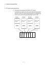
CPU module locations in a Multiple CPU system is either of the
following.
(1) There are non-installation slots between the CPU modules.
(2) The modules except the PLC CPU are installed between the PLC
CPU modules.
(1) There must be non-installation slots between the CPU
modules in the Multiple CPU system. (When the non-
installation slots are reserved, cancel the reservation.)
(2) Remove the modules except the PLC CPU installed between
the PLC CPU modules, and shift over to the slots with the
PLC CPU modules in the Multiple CPU system.
: It occurs in the CPU (CPU No.) which detected a error.
: It occurs in all CPU No. at the time of the Multiple CPU composition.
: It does not occur.