


3 - 27
3 COMMON PARAMETERS
(3) Extension setting parameters
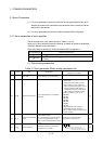
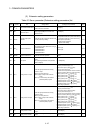
Table 3.3 Servo parameter (Extension setting parameters) list
LED
display
Symbol Item Setting details
Setting value/setting range
(Setting by setup software)
Section
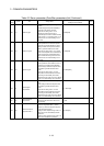
PC01 ERZ Error excessive alarm level
• Set the error excessive alarm level with
rotation amount of servomotor.
1 to 200[rev] —
PC02 MBR
Electromagnetic brake
sequence output
• Set the delay time between electronic brake
interlock signal (MBR) and the base drive
circuit is shut-off.
0 to 1000[ms] —
PC03 ENRS
Encoder output pulse
selection
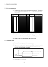
• Select the encoder output pulse direction and
encoder pulse output setting.
Encoder output pulse direction
0: A-phase increase 90° by CCW motor turning
1: A-phase increase 90° by CW motor turning
Encoder pulse output setting
0: Output pulse designation
1: Division ration setting
3.3.18
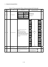
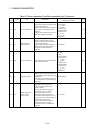
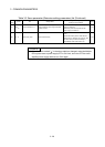
PC04 COP1 Function selection C-1
• Select the serial encoder cable.
• The following encoder cables are 4-wire type.
• MR-EKCBL30M-L
• MR-EKCBL30M-H
• MR-EKCBL40M-H
• MR-EKCBL50M-H
0: 2-wire type
1: 4-wire type
3.3.19
PC05 COP2 Function selection C-2 • Select the motor-less operation.
0: Invalid
1: Valid
3.3.20
PC07 ZSP Zero speed
• Set the output range of the zero speed
(ZSP).
• Zero speed signal detection has hysteresis
width of 20[r/min].
0 to 10000[r/min] —
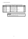
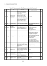
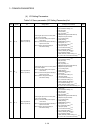
PC09 MOD1 Analog monitor 1 output
• Select the signal provided to the analog
monitor 1 output.
(Mote-1): Encoder pulse unit
(Note-2): 8[V] is output at the maximum
torque.
(Note-3): It can be used by the absolute
(absolute position) system.
0: Servomotor speed (±8V/max.speed)
1: Torque (± 8V/max.torque)
(Note-2)
2: Servomotor speed (+8V/max.speed)
3: Torque (+8V/max.torque)
(Note-2)
4: Current command (±8V/max.current command)
5: Speed command (±8V/max. speed command)
6: Droop pulses (±10V/1
10
2
[PLS])
(Note-1)
7: Droop pulses (±10V/1 10
3
[PLS])
(Note-1)
8: Droop pulses (±10V/1 10
4
[PLS])
(Note-1)
9: Droop pulses (±10V/1 10
5
[PLS])
(Note-1)
A: Feedback position (±10V/1 10
6
[PLS])
(Note-1,3),
B: Feedback position (±10V/1 10
7
[PLS])
(Note-1,3)
C: Feedback position (±10V/1 10
8
[PLS])
(Note-1,3)
D: Bus voltage (±8V/400V)
3.3.21
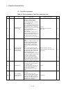
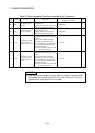
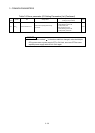
PC10 MOD2 Analog monitor 2 output
• Select the signal provided to the analog
monitor 2 output.
(Mote-1): Encoder pulse unit
(Note-2): 8[V] is output at the maximum
torque.
(Note-3): It can be used by the absolute
(absolute position) system.
0: Servomotor speed (±8V/max.speed)
1: Torque (± 8V/max.torque)
(Note-2)
2: Servomotor speed (+8V/max.speed)
3: Torque (+8V/max.torque)
(Note-2)
4: Current command (±8V/max.current command)
5: Speed command (±8V/max. speed command)
6: Droop pulses (±10V/1
10
2
[PLS])
(Note-1)
7: Droop pulses (±10V/1 10
3
[PLS])
(Note-1)
8: Droop pulses (±10V/1 10
4
[PLS])
(Note-1)
9: Droop pulses (±10V/1 10
5
[PLS])
(Note-1)
A: Feedback position (±10V/1 10
6
[PLS])
(Note-1,3),
B: Feedback position (±10V/1 10
7
[PLS])
(Note-1,3)
C: Feedback position (±10V/1 10
8
[PLS])
(Note-1,3)
D: Bus voltage (±8V/400V)
3.3.22
PC11 MO1 Analog monitor 1 offset
• Set the offset voltage of the analog monitor 1
output.
-999 to 999[mV] —
PC12 MO2 Analog monitor 2 offset
• Set the offset voltage of the analog monitor 2
output.
-999 to 999[mV] —