


2 - 14
2 MULTIPLE CPU SYSTEM
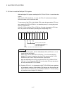
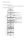
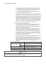
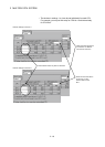
Processing details of CPU No.2 (Motion CPU) at main cycle processing.
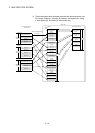
2) : Data of transmitting devices B20 to B3F for CPU No.2 is transferred to
the automatic refresh area of shared memory in the self CPU.
3) : Data in the automatic refresh area of shared memory in CPU No.1 is
transferred to B0 to B1F in the self CPU.
By the above operations, the data written to B0 to B1F in CPU No.1 can be
read as B0 to B1F of CPU No.2, while the data written to B20 to B3F in CPU
No.2 can be read as B20 to B3F of CPU No.1. B0 to B1F of CPU No.1 can
be read or written freely using CPU No.1, but B20 to B3F correspond to the
refresh area for the data of CPU No.2 and can only be read, not written, by
CPU No. 1. Similarly, B20 to B3F of CPU No.2 can be read or written freely
using CPU No.2, but B0 to B1F correspond to the refresh area for the data
of CPU No.1 and thus can only be read, not written, by CPU No.2.
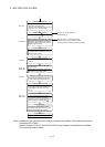
(b) Executing the automatic refresh function
The automatic refresh function can be executed regardless of whether the
applicable PLC CPU and Motion CPU are in the RUN or STOP state.
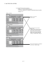
When a CPU DOWN error will occur in the PLC CPU or Motion CPU, the
automatic refresh function is not executed.
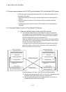
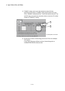
When one CPU generated a CPU DOWN error, the other CPU free from
CPU DOWN error retains the data saved immediately before the CPU
DOWN error occurred. For example, if CPU No.2 generated a CPU DOWN
error while B20 was ON in the operation block diagram in (a), B0 of CPU
No.1 remains ON. If necessary, interlocking is performed using other-CPU
DOWN detection signals M9244 to M9247.
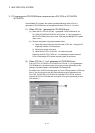
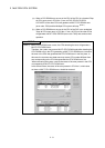
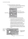
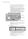
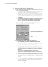
(c) To execute the automatic refresh function, for the Motion CPU the number of
transmitting points for the CPU and the devices whose data is stored
(devices to which the automatic refresh function is executed) must be set in
Multiple CPU Settings of System Settings. For the PLC CPU, the applicable
parameters must be set identically in Multiple CPU Settings of PC
parameters.
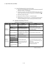
Item Description
Bit
Y, M, B (Set the first device No. as a multiple of 16 in
modules of 32 bits.)
Type of refresh device
Word D, W, # (Set in modules of 2 words.)
Number of refresh device range settings 4 ranges (Bit and word may be mixed.)
Number of refresh words per CPU A maximum of 8k words
Number of transmitting words per CPU A maximum of 2k words (Set in units of 2 words.)
CAUTION
If necessary, perform interlocking during the execution of the automatic refresh function using
other CPU DOWN detection signals M9244 to M9247.