3 - 37
3 COMMON PARAMETERS
3.3.20 Function selection C-2
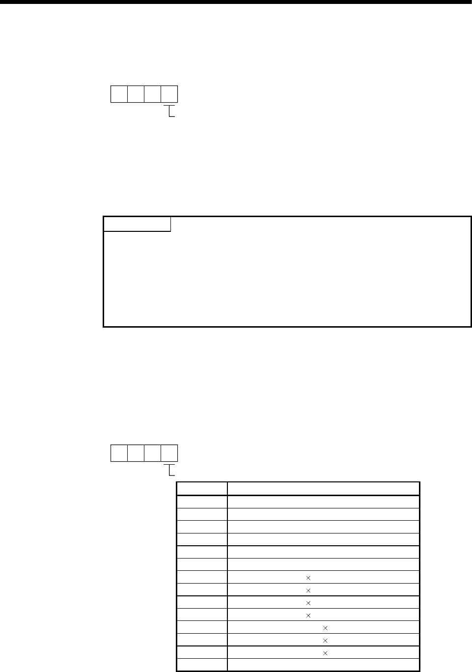
This parameter is used to select the motor-less operation.
000
Motor-less operation selection
0: Valid
1: Invalid
If motor-less operation is set to valid, the output signal can be output and status display
is possible as well as the case in which the motor operates actually without connecting
the servomotor.
It can be checked the Motion SFC program (SV13/SV22)/Motion program (SV43) of
Multiple CPU system without connecting a motor.
POINT
Function selection C-2 (Motor-less operation selection)
Motor-less operation differs from operation in which an actual motor is run in that, in
response to signals input in motor-less operation, motor operation is simulated and
output signals and state display data are created under the condition that the load
torque zero and moment of load inertia are the same as the motor's moment of
inertia. Accordingly, the acceleration/deceleration time and effective torque or the
peak load display value and the regenerative load ratio is always "0", which is not
the case when the real motor is operated.
3.3.21 Analog monitor 1 output
This parameter is used to output the operating status of servo amplifier to analog
monitor in real time. The operating status can be checked by anaolg output.
This function is used to monitor the status of servo amplifier using an ammeter or
synchronize the torque/speed with the other servo amplifiers.
Set the signal provided to the analog monitor 1 output.
000
Analog monitor 1 output
Setting value Setting details
0 Servomotor speed (±8V/max. speed)
1 Torque (±8V/max. torque)
(Note-2)
2 Servomotor speed (+8V/max. speed)
3 Torque (+8V/max. torque)
(Note-2)
4 Current command (±8V/max. current command)
5 Speed command (±8V/max. speed command)
6 Droop pulses (±10V/1 10
2
[PLS])
(Note-1)
7 Droop pulses (±10V/1 10
3
[PLS])
(Note-1)
8 Droop pulses (±10V/1 10
4
[PLS])
(Note-1)
9 Droop pulses (±10V/1 10
5
[PLS])
(Note-1)
A Feedback position (±10V/1 10
6
[PLS])
(Note-1,3),
B Feedback position (±10V/1 10
7
[PLS])
(Note-1,3)
C Feedback position (±10V/1 10
8
[PLS])
(Note-1,3)
D Bus voltage (±8V/400V)
(Note-1): Encoder pulse unit
(Note-2): 8[V] is output at the maximum torque.
(Note-3): It can be used by the absolute (absolute position) system.


