


3 - 29
3 COMMON PARAMETERS
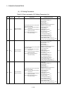
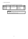
(4) I/O Setting Parameters
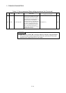
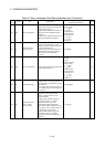
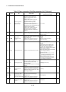
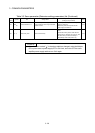
Table 3.4 Servo parameter (I/O Setting Parameters) list
LED
display
Symbol Item Setting details
Setting value/setting range
(Setting by setup software)
Section
PD07 DO1
Output signal device
selection 1 (CN3-13)
• Set the signal output to the connector (CN3-
13 pin) of servo amplifier.
(Mote-1): It becomes always OFF in speed
control mode.
(Note-2): It becomes SA (Speed reached) in
speed control mode.
(Note-3): Never change this setting for
manufacturer setting.
00: Always OFF
01: For manufacturer setting
(Note-3)
02: RD (Servo ON)
03: ALM (Trouble)
04: INP (In-position)
(Note-1)
05: MBR (Electromagnetic brake interlock)
06: DB (External dynamic brake)
07: TLC (Limiting torque)
08: WNG (Warning)
09: RWNG (Battery warning)
0A: Always OFF
(Note-2)
0B: For manufacturer setting
(Note-3)
0C: ZSP (Zero speed)
0D: For manufacturer setting
(Note-3)
0E: For manufacturer setting
(Note-3)
0F: CDPS (Variable gain selection)
10: For manufacturer setting
(Note-3)
11: ABSV (Absolute position erasing)
(Note-1)
12 to 1F, 20 to 3F: For manufacturer setting
(Note-3)
3.3.25
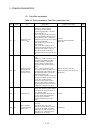
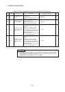
PD08 DO2
Output signal device
selection 2 (CN3-9)
• Set the signal output to the connector (CN3-9
pin) of servo amplifier.
(Mote-1): It becomes always OFF in speed
control mode.
(Note-2): It becomes SA (Speed reached) in
speed control mode.
(Note-3): Never change this setting for
manufacturer setting.
00: Always OFF
01: For manufacturer setting
(Note-3)
02: RD (Servo ON)
03: ALM (Trouble)
04: INP (In-position)
(Note-1)
05: MBR (Electromagnetic brake interlock)
06: DB (External dynamic brake)
07: TLC (Limiting torque)
08: WNG (Warning)
09: RWNG (Battery warning)
0A: Always OFF
(Note-2)
0B: For manufacturer setting
(Note-3)
0C: ZSP (Zero speed)
0D: For manufacturer setting
(Note-3)
0E: For manufacturer setting
(Note-3)
0F: CDPS (Variable gain selection)
10: For manufacturer setting
(Note-3)
11: ABSV (Absolute position erasing)
(Note-1)
12 to 1F, 20 to 3F: For manufacturer setting
(Note-3)
3.3.26
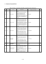
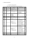
PD09 DO3
Output signal device
selection 3 (CN3-15)
• Set the signal output to the connector (CN3-
15 pin) of servo amplifier.
(Mote-1): It becomes always OFF in speed
control mode.
(Note-2): It becomes SA (Speed reached) in
speed control mode.
(Note-3): Never change this setting for
manufacturer setting.
00: Always OFF
01: For manufacturer setting
(Note-3)
02: RD (Servo ON)
03: ALM (Trouble)
04: INP (In-position)
(Note-1)
05: MBR (Electromagnetic brake interlock)
06: DB (External dynamic brake)
07: TLC (Limiting torque)
08: WNG (Warning)
09: RWNG (Battery warning)
0A: Always OFF
(Note-2)
0B: For manufacturer setting
(Note-3)
0C: ZSP (Zero speed)
0D: For manufacturer setting
(Note-3)
0E: For manufacturer setting
(Note-3)
0F: CDPS (Variable gain selection)
10: For manufacturer setting
(Note-3)
11: ABSV (Absolute position erasing)
(Note-1)
12 to 1F, 20 to 3F: For manufacturer setting
(Note-3)
3.3.27